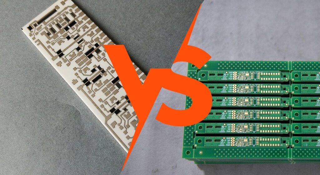
Ceramic PCB and FR4 are main substrate on market.
FR4 is the standard substrate for most commercial electronics because it is affordable, scalable, and easy to manufacture.
Ceramic PCBs become more attractive when heat, power density, temperature stability, or long-term reliability becomes difficult to manage.
Ceramic is not automatically the better choice. The right substrate depends on thermal, electrical, mechanical, manufacturing, and cost requirements.
This guide compares ceramic PCB vs FR4 using representative data from established laminate and technical ceramic manufacturers.
Quick Answer
|
Design Requirement |
Best Starting Point |
Reason |
|
General Control Electronics |
FR4 |
Low cost, mature processes, and flexible multilayer routing |
|
Dense Digital Or HDI Board |
FR4 |
Better suited to complex stackups and fine-pitch routing |
|
Moderate LED Or Power Load |
MCPCB or high-Tg FR4 |
Improved heat management without ceramic cost |
|
High-Power LED Or Laser Module |
Ceramic |
Heat must move through the substrate efficiently |
|
IGBT, Sic, Or Gan Power Module |
Ceramic |
Strong thermal performance and electrical isolation |
|
High-Voltage, High-Heat System |
Ceramic |
Better suited to combined thermal and insulation demands |
|
RF Or Microwave Circuit |
Evaluate RF laminate first |
Low loss may matter more than thermal conductivity |
FR4 is usually the better option when copper planes, thermal vias, a heat sink, or the enclosure can manage the heat. Ceramic earns its cost when the substrate itself must carry the thermal load.
Table of Contents
1. What Is an FR4 PCB?
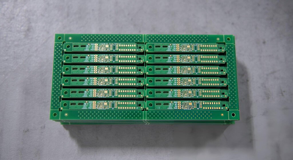
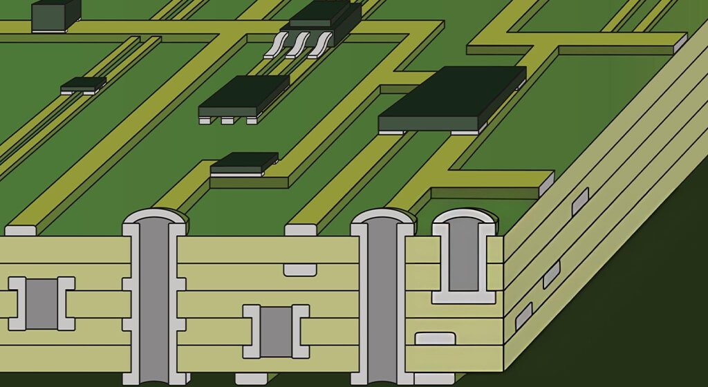
FR4 is a glass-fiber reinforced epoxy laminate used as the base material in most printed circuit boards.
Its balance of electrical insulation, mechanical strength, manufacturing maturity, and cost makes it the industry standard.
Modern FR4 systems support simple two-layer boards and advanced multilayer designs with controlled impedance and HDI structures.
They also work with established drilling, plating, lamination, etching, solder-mask, and assembly processes.
2. What Is a Ceramic PCB?
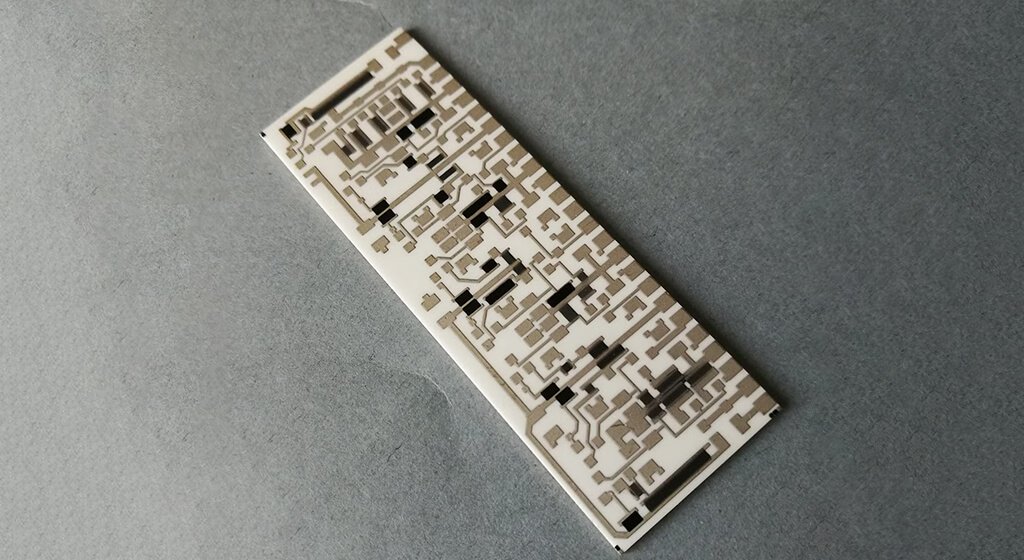
Ceramics PCBs uses technical ceramic as the main insulating substrate instead of glass-reinforced epoxy laminate.
Common materials include alumina, aluminum nitride, and silicon nitride for demanding electronic and power applications.
Ceramics combine electrical insulation with thermal and dimensional properties that organic laminates cannot always provide.
However, each ceramic material has different performance characteristics, manufacturing requirements, and costs.
For a deeper material comparison, read PCBSAIL’s Complete Guide to Ceramic PCB Materials.
2.1. Alumina Ceramic PCB
Alumina, or Al₂O₃, is among the most widely used technical ceramics for electronic substrates.
It offers a practical balance of thermal performance, electrical insulation, mechanical strength, availability, and cost.
KYOCERA reports thermal conductivity values between 14 and 24 W/m·K across selected alumina substrate grades.
The same material family lists CTE values around 6.9 to 7.5 ppm/K from room temperature to 400°C.
Alumina was used in lighting, optical communications, electronics packaging, and other heat-generating devices.
2.2. Aluminum Nitride Ceramic PCB
Aluminum nitride offers much higher thermal conductivity while maintaining strong electrical insulation.
AlN is an best choice for compact devices that produce substantial heat within electrically isolated structures.
KYOCERA reports thermal conductivity values between 150 and 240 W/m·K for selected AlN substrate grades.
Its published CTE values are approximately 4.6 to 4.8 ppm/K between room temperature and 400°C.
AlN is commonly considered for high-power devices, light sources, lasers, and other thermally demanding applications.
2.3. Silicon Nitride Ceramic
Silicon nitride, or Si₃N₄, is useful when thermal performance and mechanical reliability both matter.
It offers a different balance than alumina or aluminum nitride, especially under demanding thermal cycling.
KYOCERA reports 54 W/m·K thermal conductivity at 20°C for its SN241O silicon nitride grade.
The same material lists a CTE of 2.9 × 10⁻⁶/K between 40°C and 400°C.
3. Ceramic PCB vs FR4 Thermal Conductivity
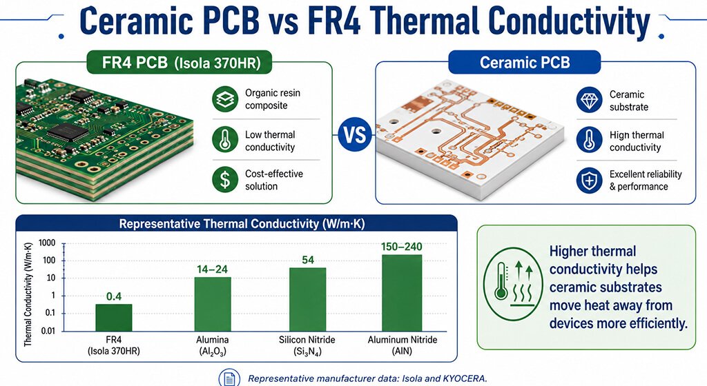
Thermal conductivity is usually the first specification engineers compare when evaluating ceramic PCB vs FR4.
The difference can be substantial, especially when comparing FR4 with aluminum nitride.
Isola reports 0.4 W/m·K thermal conductivity for its 370HR high-Tg FR4 laminate.
KYOCERA reports 14–24 W/m·K for selected alumina grades and 150–240 W/m·K for selected AlN grades.
Material | Representative Thermal Conductivity | Source |
Isola 370HR FR4 | 0.4 W/m·K | Isola 370HR datasheet |
Alumina Al₂O₃ | 14–24 W/m·K | Selected KYOCERA substrate grades |
Silicon Nitride Si₃N₄ | 54 W/m·K | KYOCERA SN241O at 20°C |
Aluminum Nitride AlN | 150–240 W/m·K | Selected KYOCERA substrate grades |
We have known why ceramic substrates are widely considered for demanding thermal-management applications.
However, thermal conductivity alone does not determine the final junction temperature inside an electronic assembly.
4. Ceramic PCB vs FR4 CTE and Thermal Cycling
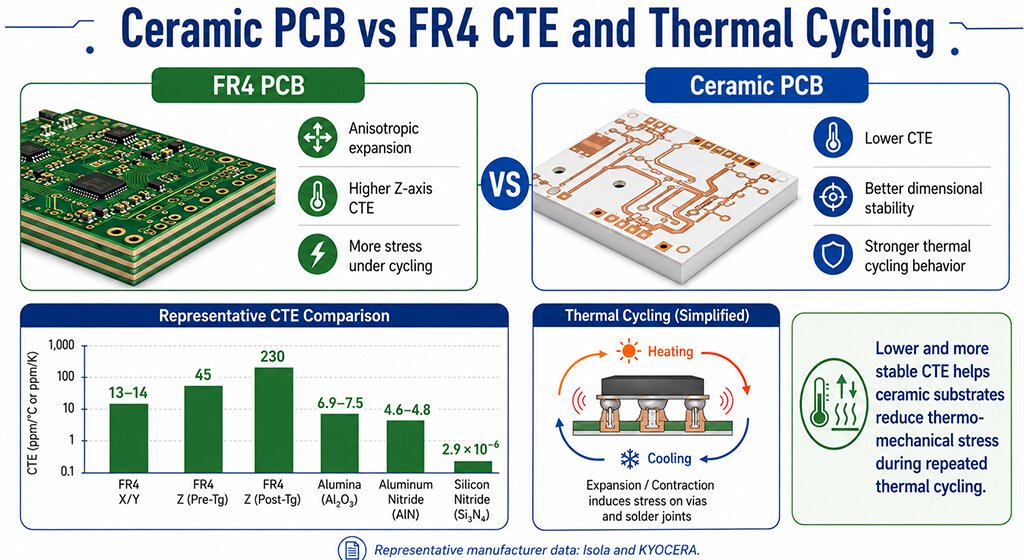
The coefficient of thermal expansion describes how much a material changes dimension as temperature changes.
CTE becomes important when materials with different expansion rates are bonded together inside an electronic assembly.
FR4 is anisotropic, meaning its expansion differs between in-plane and through-thickness directions.
Ceramic substrates generally offer lower and more stable thermal expansion than typical organic laminates.
Material | Representative CTE | Conditions |
Isola 370HR FR4 X/Y | 13/14 ppm/°C | Pre-Tg |
Isola 370HR FR4 Z-axis | 45 ppm/°C | Pre-Tg |
Isola 370HR FR4 Z-axis | 230 ppm/°C | Post-Tg |
Alumina | 6.9–7.5 ppm/K | RT–400°C |
Aluminum Nitride | 4.6–4.8 ppm/K | RT–400°C |
Si₃N₄ SN241O | 2.9 × 10⁻⁶/K | 40–400°C |
The ceramic values above come from selected KYOCERA substrate grades and are not universal material constants.
4.1. Why Does CTE Matter?
Different expansion rates create mechanical stress when semiconductor dies, copper, solder, and substrates heat together.
Repeated thermal cycling can challenge interfaces, solder joints, vias, and bonded structures over time.
Lower substrate CTE can help, but it does not guarantee better reliability in every ceramic assembly.
Copper thickness, metallization, bonding technology, solder systems, and package architecture still influence long-term performance.
Power module designers should evaluate completed thermo-mechanical behavior rather than individual substrate values alone.
5. Ceramic PCB vs FR4 Electrical Performance
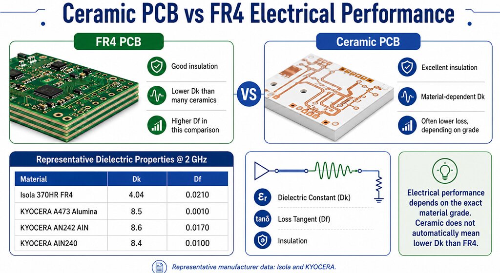
Both FR4 and ceramic substrates provide electrical insulation, but their dielectric behavior varies widely by material.
It is misleading to claim that every ceramic automatically outperforms every FR4 system electrically.
Material | Representative Dk at 2 GHz | Representative Df at 2 GHz |
Isola 370HR FR4 | 4.04 | 0.0210 |
KYOCERA A473 Alumina | 8.5 | 0.0010 |
KYOCERA AN242 AlN | 8.6 | 0.0170 |
KYOCERA AlN240 | 8.4 | 0.0100 |
These values come from different manufacturer datasets and may use different test conditions.
They should guide material selection rather than serve as a strict laboratory-controlled comparison.
6. Ceramic PCB vs FR4 for High-Frequency and RF Applications
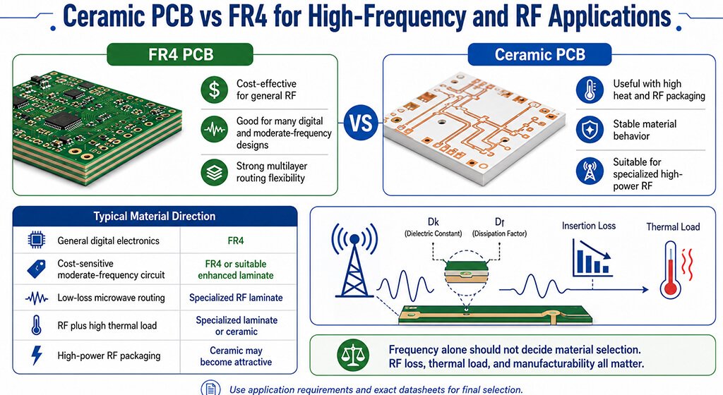
Standard FR4 is still suitable for many digital circuits and lower-frequency applications requiring economical multilayer manufacturing.
Advance RF designs may need lower loss, stable dielectric properties, or better thermal performance.
Ceramic substrates can become attractive when RF performance combines with high heat generation or strict packaging limits.
However, specialized high-frequency organic laminates may still be better for many microwave transmission structures.
Frequency alone should not decide whether a designer uses ceramic PCB or FR4.
Application Requirement | Typical Material Direction |
General Digital Electronics | FR4 |
Cost-Sensitive Moderate-Frequency Circuit | FR4 or suitable enhanced laminate |
Low-Loss Microwave Routing | Specialized RF laminate |
RF Plus High Thermal Load | Specialized laminate or ceramic |
High-Power RF Packaging | Ceramic may become attractive |
Final selection should consider Dk, Df, copper roughness, impedance stability, insertion loss, thermal load, and manufacturability.
7. Ceramic PCB vs FR4 Mechanical Properties
Ceramic substrates are hard, stable, and well suited to many harsh thermal and chemical environments.
However, ceramics are also more brittle than glass-reinforced epoxy laminates and require careful mechanical design.
FR4 is generally more forgiving during drilling, routing, handling, assembly, and conventional PCB manufacturing.
Its mature fabrication ecosystem also makes complex multilayer structures easier and more economical to produce.
8. Ceramic PCB vs FR4 Cost
FR4 is usually more economical because its materials, equipment, and production processes are highly standardized.
Ceramic PCB manufacturing requires more specialized substrates, metallization, bonding, and process control.
Costs also vary significantly among alumina, AlN, Si₃N₄, copper structures, tolerances, and production volumes.
Processes such as DBC, DPC, or AMB can also change total manufacturing cost.
Comparing only PCB unit prices can still lead to the wrong engineering decision.
9. When Should You Choose FR4 Instead?
FR4 remains the best default choice for a wide range of electronic products.
Do not select ceramic simply because its thermal conductivity number looks more impressive.
Choose FR4 when thermal requirements are moderate and conventional cooling techniques can meet temperature targets economically.
FR4 also remains attractive when dense multilayer routing and advanced via structures dominate the design.
FR4 is usually preferable when:
- Production cost is highly sensitive
- Complex multilayer routing is required
- Fine signal interconnection dominates
- Thermal loads remain manageable
- Fast prototyping is important
- Large production volumes are expected
- Standard PCB assembly processes are preferred
For these applications, PCBSAIL provides FR-4 PCB prototype and production services.
10. Ceramic PCB vs FR4 by Application
Material selection becomes easier when substrate properties are connected directly with real application requirements.
Application | FR4 Suitability | Ceramic Suitability | Typical Direction |
Consumer Electronics | Excellent | Usually unnecessary | FR4 |
Industrial Control | Excellent | Application-dependent | Usually FR4 |
Computing Hardware | Excellent | Specialized cases | FR4 |
Low-Power LED | Good | Usually unnecessary | FR4 or MCPCB |
High-Power LED | Limited by thermal design | Strong | MCPCB or ceramic |
Power Electronics | Depends on power density | Strong | Application-dependent |
EV Power Modules | Limited for demanding modules | Strong | Ceramic often considered |
SiC/GaN Power Systems | Challenging at high density | Strong | Ceramic often considered |
RF Electronics | Application-dependent | Application-dependent | FR4, RF laminate, or ceramic |
Aerospace Electronics | Requirement-dependent | Strong candidate | Engineering-specific |
Medical Electronics | Requirement-dependent | Strong candidate | Engineering-specific |
These recommendations are starting points rather than fixed rules for every product.
11. Ceramic PCB vs FR4: How Should Engineers Choose?
Material selection should start with application requirements rather than the most impressive number on a datasheet.
11.1. How Much Heat Must the PCB Remove?
Estimate component losses, heat density, junction limits, and maximum allowable substrate temperature under realistic conditions.
11.2. What Is the Complete Thermal Path?
Identify every interface between the semiconductor junction and the final heat sink, cold plate, or ambient air.
11.3. Do You Need Complex Multilayer Routing?
FR4 generally provides greater flexibility for dense multilayer interconnection and conventional PCB routing structures.
11.4. What Electrical Performance Is Required?
Check insulation, dielectric constant, dielectric loss, impedance, voltage, and operating frequency using specific datasheets.
11.5. What Is the Total System Budget?
Compare manufacturing, cooling, assembly, reliability, and lifecycle costs instead of comparing substrate prices alone.
12. FAQ
Is Ceramic PCB Better Than FR4?
Ceramic is better when thermal performance, electrical isolation, or demanding reliability requirements justify specialized materials.
FR4 is better for many cost-sensitive multilayer products requiring flexible routing and established manufacturing processes.
Why Is Ceramic PCB More Expensive Than FR4?
Ceramic PCB materials and manufacturing processes are more specialized than conventional high-volume FR4 production.
Cost also depends on ceramic type, copper structure, metallization, tolerances, quantity, and testing requirements.
Can FR4 Be Used For High-Power Electronics?
Yes, FR4 can support many power applications when copper design, thermal vias, airflow, and cooling remain sufficient.
Higher power density may require MCPCB, IMS, ceramic substrates, or other specialized packaging solutions.
Is MCPCB Cheaper Than Ceramic PCB?
MCPCB is generally positioned between FR4 and advanced ceramic solutions in both cost and thermal capability.
Actual pricing depends on materials, layer structure, dimensions, copper thickness, volume, and manufacturing requirements.
Should I Compare Tg When Choosing Between Ceramic PCB And FR4?
Tg is useful, but it does not represent continuous operating temperature by itself.
Review RTI, MOT, material datasheets, assembly limits, and reliability requirements before selecting the final substrate.
13. Final
FR4 is the most economical and flexible substrate for most conventional electronics.
Ceramic becomes more valuable when thermal conductivity, electrical isolation, dimensional stability, or reliability becomes critical.
Alumina offers a balanced ceramic option, while AlN targets much more demanding thermal applications.
Do not choose a substrate based on thermal conductivity alone.
Thermal resistance, CTE mismatch, electrical behavior, manufacturing process, and total system cost matter just as much.
For many designs, the practical path moves from FR4 to enhanced FR4, MCPCB, IMS, or ceramic.
The right choice depends on the problem the substrate must solve.