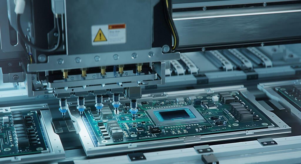
Modern electronics rely on efficient PCB assembly technologies. Whether you are developing an IoT device, industrial controller, medical instrument, automotive ECU, or aerospace system, the assembly method directly affects product cost, reliability, performance, and manufacturability.
The two most widely used PCB assembly methods are:
Although SMT dominates modern electronics manufacturing, through-hole assembly also plays an important role in many applications requiring superior mechanical strength and durability.
This guide explains the differences between SMT and through-hole assembly, their advantages, limitations, costs, reliability factors, and how to choose the best solution for your project.
Table of Contents
1. What Is SMT Assembly?
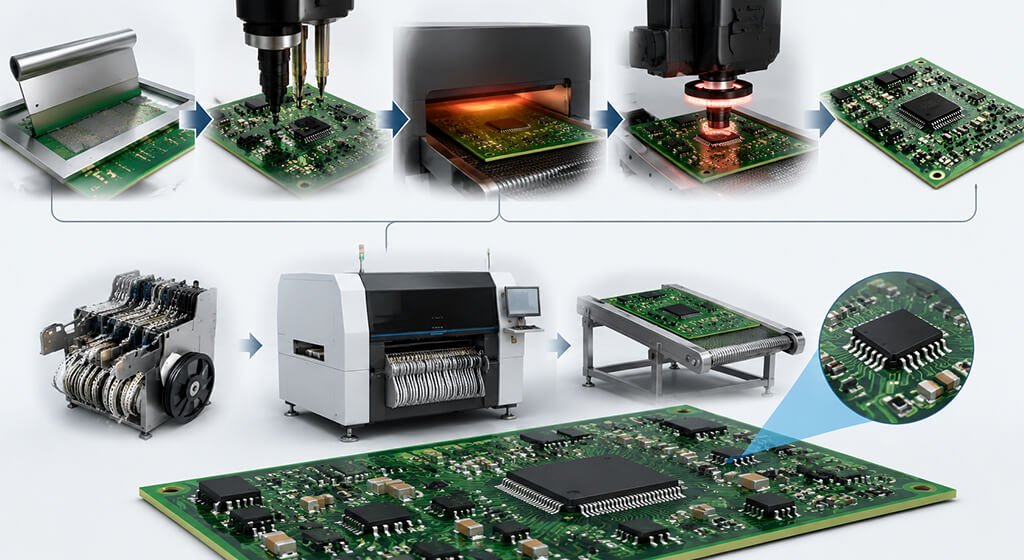
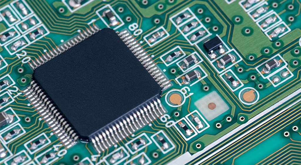
SMT (Surface Mount Technology) is a PCB assembly process where electronic components are mounted directly onto the surface of a printed circuit board.
The components used are called Surface Mount Devices (SMDs).
Instead of inserting component leads through drilled holes, SMT components are soldered directly onto copper pads.
1.1. SMT Assembly Process
Typical SMT Production Includes:
Solder Paste Printing
Component Placement
Reflow Soldering
AOI Inspection
X-Ray Inspection (For Bgas)
Functional Testing
Modern SMT lines can place tens of thousands of components per hour.
According to major SMT assembly service supplier, automated SMT placement machines can achieve placement accuracy below ±30 μm while reaching speeds exceeding 50,000–100,000 components per hour.
1.2. SMT Assembly Advantages
1.2.1. Smaller Product Size
One of the biggest advantages of SMT is miniaturization. SMD components are significantly smaller than through-hole components.
It Allows Engineers To:
- Reduce Board Size
- Increase Functionality
- Lower Product Weight
For smartphones, wearables, drones, and IoT devices, SMT is the only practical solution.
1.2.2. Higher Component Density
SMT enables components to be mounted on both sides of a PCB. It dramatically increases circuit density.
Benefits Include:
- More Functionality
- Reduced PCB Dimensions
- Better Signal Routing
- Lower Material Usage
Modern HDI PCBs depend heavily on SMT technology.
1.2.3. Lower Manufacturing Cost
Automated SMT production significantly reduces labor costs. SMT assembly can reduce assembly labor requirements by up to 60–80% compared with manual through-hole assembly.
Benefits Include:
- Faster Production
- Lower Labor Costs
- Reduced Assembly Errors
- Better Consistency
For medium and high-volume production, SMT offers substantial cost savings.
1.2.4. Faster Production Speed
Modern pick-and-place machines can install thousands of components every minute.
It Enables:
- Rapid Prototyping
- High-Volume Manufacturing
- Shorter Lead Times
Large electronics manufacturers rely on SMT because of its scalability.
1.2.5. Better High-Frequency Performance
SMT components have shorter leads.
Shorter Electrical Paths Result In:
- Lower Parasitic Inductance
- Reduced Signal Distortion
- Improved RF Performance
This Makes SMT Ideal For:
- 5G Systems
- RF Circuits
- High-Speed Digital Devices
- Telecommunications Equipment
1.3. SMT Assembly Disadvantages
Despite its advantages, SMT has limitations.
1.3.1. Reduced Mechanical Strength
SMD components are attached only to PCB surface pads. Under mechanical stress, components may detach more easily than through-hole components.
It Becomes Important In:
- Vibration Environments
- Automotive Systems
- Heavy Equipment
1.3.2. Difficult Manual Repair
SMT components are very small.
Repair Often Requires:
- Hot Air Stations
- Microscopes
- Skilled Technicians
Complex packages such as BGA devices require specialized rework equipment.
1.3.3. Thermal Stress Concerns
During reflow soldering, components experience elevated temperatures.
Improper Thermal Management Can Cause:
- Solder Defects
- Component Damage
- Warpage
Proper process control is essential.
Do You Need Any Help?
2. What Is Through-Hole Assembly?
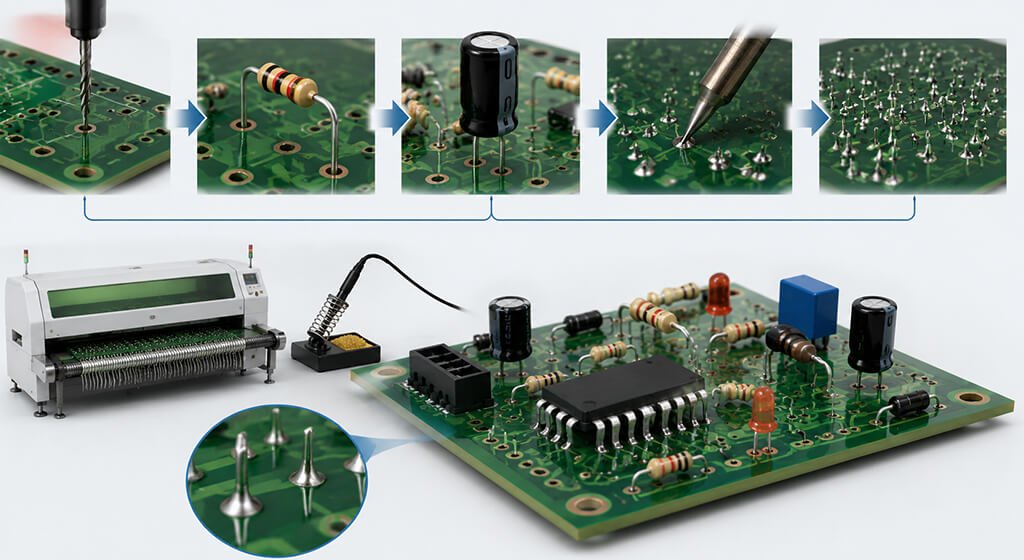
Through-Hole Technology (THT) is the traditional PCB assembly method. Component leads are inserted through drilled holes in the PCB and soldered on the opposite side.
THT Components Typically Include:
- Connectors
- Transformers
- Large Capacitors
- Relays
- Power Semiconductors
- High-Current Components
Although less common than SMT, through-hole assembly remains important in high-reliability applications.
2.1. Through-Hole Assembly Advantages
2.1.1. Superior Mechanical Strength
It is the biggest advantage of through-hole assembly. Component leads pass completely through the PCB. The resulting solder joints provide excellent structural support.
THT Is Ideal For:
- Connectors
- Switches
- Transformers
- Heavy Components
2.1.2. Better Reliability Under Vibration
As our experience, through-hole connections perform exceptionally well under vibration and shock.
Applications Include:
- Aircraft Electronics
- Defense Systems
- Railway Electronics
- Industrial Machinery
2.1.3. Easier Prototyping
Through-hole components are easier to handle manually.
Engineers Often Use THT During:
- Product Development
- Laboratory Testing
- Educational Projects
Soldering and replacement are straightforward.
2.1.4. Better High-Power Handling
Power electronics often require larger components.
Examples:
- Large Capacitors
- Transformers
- Inductors
- Power Connectors
Through-hole mounting provides superior current-carrying capability and heat dissipation.
2.1.5. Simplified Inspection
Through-hole solder joints are usually visible. Visual inspection becomes easier compared with hidden SMT joints. It reduces troubleshooting complexity.
2.2. Through-Hole Assembly Disadvantages
Despite its advantages, SMT has limitations.
2.2.1. Higher Manufacturing Cost
THT Assembly Requires:
- Drilling Holes
- Additional Materials
- More Labor
These factors increase production expenses.
2.2.2. Slower Production
Many through-hole operations remain partially manual.
As A Result:
- Assembly Speed Decreases
- Labor Costs Increase
- Scalability Becomes Challenging
2.2.3. Larger PCB Size
Through-hole components occupy more space.
Designers Often Require:
- Larger Boards
- Additional Layers
- Increased Material Usage
3. SMT vs Through-Hole Assembly: Key Differences
Feature | SMT Assembly | Through-Hole Assembly |
Component Mounting | Surface of PCB | Through drilled holes |
Assembly Speed | Very fast | Slower |
Automation Level | Highly automated | Partially automated |
PCB Size | Smaller | Larger |
Component Density | High | Lower |
Manufacturing Cost | Lower at scale | Higher |
Mechanical Strength | Moderate | Excellent |
Repairability | Difficult | Easier |
High-Frequency Performance | Excellent | Moderate |
High-Power Applications | Limited | Excellent |
Do You Need Any Help?
4. High-Frequency and Thermal Performance Analysis
When selecting between Surface Mount Technology (SMT) and Through-Hole Technology (THT), engineers should evaluate several key performance factors beyond simply manufacturing cost. The right choice depends on electrical requirements, mechanical stresses, environmental conditions, and production goals.
Performance Factor | SMT | THT | Typical Industry Data |
Component Size | Extremely small packages (01005, 0201, 0402) | Typically larger packages | SMT components can be over 90% smaller than equivalent THT components |
Component Density | Very High | Moderate | SMT enables 2–10× higher component density than THT |
PCB Size Reduction | Excellent | Limited | SMT can reduce PCB area by 30–70% |
Placement Speed | Fully automated | Partially automated | Modern SMT machines: 50,000–120,000 CPH (components per hour) |
Placement Accuracy | Extremely precise | Manual/semi-automatic | ±25–30 μm for advanced SMT equipment |
Production Volume | Ideal for mass production | Better for low-volume/specialized products | SMT lines can run 24/7 with minimal operator intervention |
Assembly Cost | Lower at scale | Higher | SMT labor costs are typically 40–80% lower than THT |
Drilling Requirements | Minimal | Extensive | THT may require hundreds or thousands of holes per board |
Electrical Performance | Excellent | Good | Lead lengths reduced by 70–95% compared with THT |
Parasitic Inductance | Low | Higher | SMT can reduce parasitic inductance by 60–90% |
Signal Integrity | Excellent | Moderate | SMT preferred for >1 GHz RF and high-speed digital circuits |
Maximum Operating Frequency | Superior | Limited | Nearly all modern RF, 5G, and high-speed computing designs use SMT |
Mechanical Strength | Good | Excellent | THT joints typically withstand higher pull and shear forces |
Shock Resistance | Good | Excellent | THT preferred for aerospace and military applications |
Vibration Resistance | Good | Excellent | NASA and aerospace standards frequently specify THT for mission-critical connectors |
Thermal Dissipation | Good | Excellent for large power devices | THT leads provide additional heat conduction paths |
Current Carrying Capability | Moderate | Excellent | High-current connectors and transformers typically use THT |
Repairability | Difficult | Easy | THT components are easier to remove and replace manually |
Automation Compatibility | Excellent | Moderate | SMT supports SPI, AOI, X-ray, MES, and smart factory integration |
Inspection Complexity | Moderate | Simple | Hidden SMT joints often require AOI/X-ray inspection |
Typical Market Share | Dominant | Specialized | SMT accounts for 90%+ of electronic assembly worldwide |
5. Total Cost of Ownership (TCO) and Production Economics
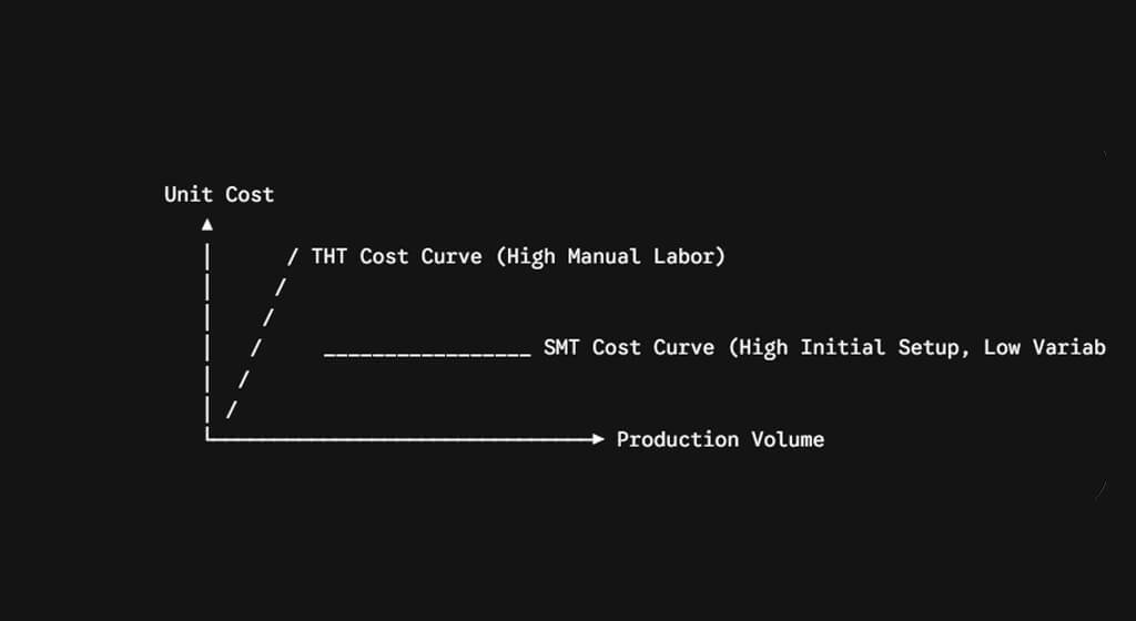
When optimizing for procurement and supply chain efficiency, cost curves vary dramatically based on production volume.
5.1. Initial Capital Expenditure (CapEx) and Setup
- SMT: Requires high initial investment. Photolithographic stencils must be cut, and pick-and-place files must be accurately programmed. Tooling modifications incur higher NRE (Non-Recurring Engineering) fees.
- THT: Requires minimal setup costs. For low-volume prototypes, manual assembly completely avoids the need for expensive stencils or machine optimization.
5.2. Scaling and Volume Break-Even Points
- Low Volume (1–100 units): THT or manual/semi-automated SMT is highly economical. The labor cost is lower than the engineering setup cost of high-speed SMT lines.
- High Volume (1,000+ units): SMT yields massive economies of scale. High-speed pick-and-place machines can mount over 100,000 components per hour (CPH), reducing variable assembly labor costs to fractions of a cent per board. Conversely, THT remains bottlenecked by manual insertion or slower wave-soldering processes, causing the cost per unit to remain flat regardless of volume.
6. Industrial Applications: When to Choose SMT vs. THT
To maximize reliability and return on investment (ROI), choices should align with specific industry standards and operating environments.
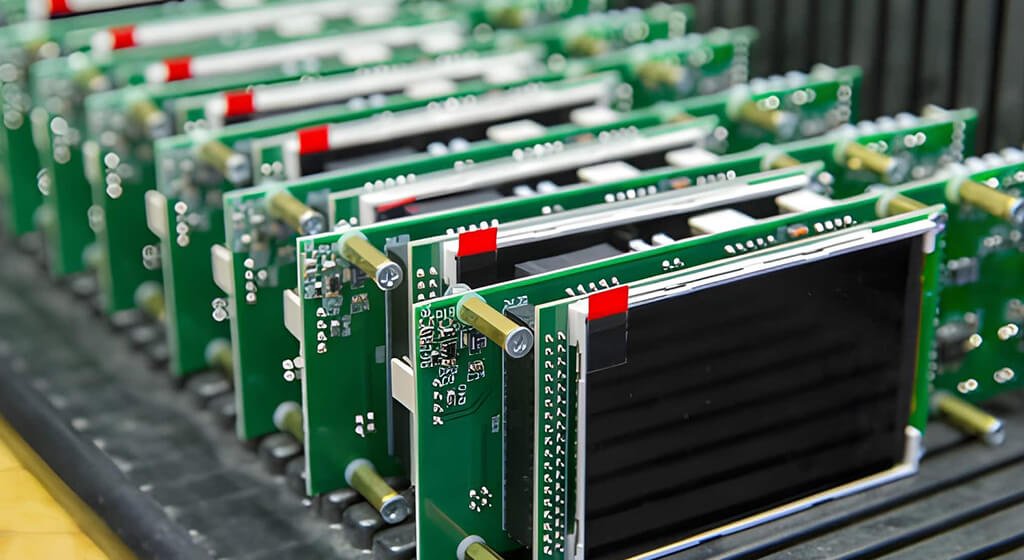
6.1. Real-World Use Cases for SMT
- Consumer Electronics & IoT: Smartphones, smartwatches, and wearables require ultra-dense, multi-layer PCBs that can only be assembled via SMT.
- High-Reliability Drone Flight Controllers: Demands lightweight architectures, high-speed processing, and compact layouts using multi-layer Polyimide or advanced FR4 substrates.
- Computing & Data Centers: High-performance motherboards, RAM modules, and GPUs utilize dense BGA packaging that cannot physicalize through holes.
6.2. Real-World Use Cases for THT
- Industrial Power Electronics: High-voltage power supplies, industrial motor drives, and inverters requiring robust mechanical connections for large transformers, relays, and electrolytic capacitors.
- Aerospace & Defense: Military hardware subjected to extreme mechanical shock, high-G acceleration, and radical thermal cycling. THT joints satisfy IPC Class 3 aerospace criteria under persistent mechanical stress.
- Automotive Systems: Under-the-hood engine control units (ECUs) and heavy-duty fuse relay boxes that must withstand severe, continuous vehicle vibration over decades.
Product Type | SMT Usage | THT Usage |
Smartphones | 99% | <1% |
Tablets | 99% | <1% |
Smart Watches | 100% | 0% |
Consumer Electronics | 95%+ | Minimal |
Networking Equipment | 90%+ | Connectors only |
Industrial Control Systems | 70–90% | 10–30% |
Automotive Electronics | 80–95% | Power components and connectors |
Aerospace Systems | Mixed | Significant |
Power Supplies | Mixed | Significant |
Motor Drives | Mixed | Significant |
Do You Need Any Help?
7. Hybrid PCB Assembly
The reality of modern PCBA manufacturing is rarely binary. Most high-performance industrial and consumer electronics utilize a Hybrid PCB Assembly process, combining the strengths of both SMT and THT on a single board.
7.1. The Mixed Assembly Process Flow
To minimize production costs and prevent thermal degradation of sensitive components, a strict manufacturing sequence must be maintained during hybrid assembly:
- SMT Solder Paste Printing: Solder paste is stenciled onto the top side pads.
- SMT Pick-and-Place: Surface mount components are placed onto the paste.
- Top-Side Reflow Soldering: The board passes through a multi-zone reflow oven to solidify SMT joints.
- Bottom-Side SMT Assembly (If applicable): The board is flipped; secondary SMDs are adhered using conductive glue or specialized paste and reflowed.
- THT Component Insertion: Through-hole components are inserted manually or via automated axial/radial insertion machinery.
- Selective or Wave Soldering: The assembled board passes over a wave soldering machine or a localized selective soldering nozzle to solder the THT pins without re-melting the top-side SMT components.
8. Final Thoughts
There is no universal winner between SMT assembly and through-hole assembly. The right choice depends on your product requirements, budget, reliability goals, and production volume.
SMT dominates modern electronics because it enables miniaturization, automation, lower costs, and superior high-frequency performance. It is the preferred solution for consumer electronics, telecommunications equipment, IoT devices, and most commercial products.
Through-hole assembly remains indispensable for applications requiring exceptional mechanical strength, vibration resistance, and high-power handling. Aerospace, defense, industrial automation, and power electronics continue to rely heavily on THT components.
For many products, the optimal solution is a hybrid PCB assembly approach that combines SMT efficiency with through-hole durability.
By understanding the strengths and limitations of each technology, engineers can design more reliable, cost-effective, and manufacturable electronic products.
Get a PCB Quote