Medical PCB assembly is not just manufacturing. It is a regulated engineering discipline governed by international safety standards, biocompatibility requirements, traceability systems, and extreme reliability expectations.
This article provides a deep breakdown of Medical PCB Assembly, including standards (IEC, FDA), materials, design constraints, failure prevention, manufacturing workflows, and emerging trends in AI-driven healthcare electronics.
Table of Contents
1. What Is Medical PCB Assembly?
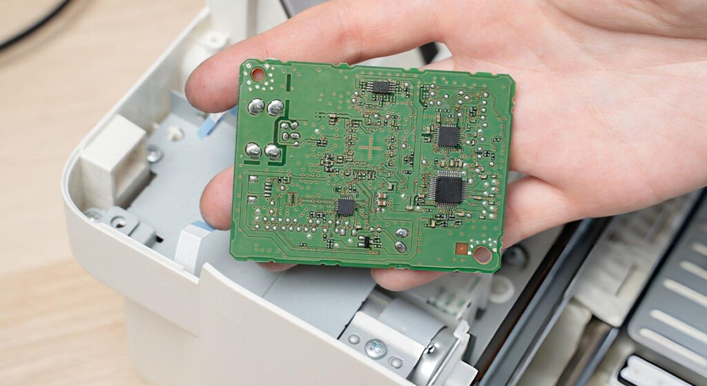
Medical PCB assembly is the process of mounting and soldering electronic components onto printed circuit boards used in medical devices such as diagnostic machines, monitoring systems, and implantable electronics.
These assemblies must meet strict requirements in:
- Electrical Reliability
- Mechanical Stability
- Biocompatibility Considerations
- Long-Term Operational Durability
2. Medical PCB Assembly Standards & Compliance
Medical PCB assembly is a high-reliability electronics manufacturing discipline used in life-supporting, diagnostic, and therapeutic systems. Unlike consumer electronics, medical devices require validated processes, full traceability, and near-zero defect tolerance.
PCB assembly is not treated as a production service, but as a regulated engineering process governed by international standards such as ISO 13485, IPC-A-610 Class 3, and FDA design controls.
2.1. ISO 13485 — Medical Device Quality Management System
ISO 13485 defines requirements for:
- Process Control In Medical Manufacturing
- Risk Management Integration
- Full Traceability Of Components And Processes
- Documented Validation Of Production Systems
ISO 13485 certification is widely recognized as a baseline requirement for medical electronics suppliers entering EU and US markets.
2.2. IPC-A-610 Class 3 — High-Reliability Acceptance Standard
IPC-A-610 Class 3 defines the highest acceptance criteria for electronic assemblies.
Key requirements include:
- Zero Tolerance For Critical Solder Defects
- Strict Inspection Of BGA, QFN, And Fine-Pitch Components
- Controlled Solder Joint Geometry And Wetting Conditions
- Mandatory Inspection Of High-Risk Interconnects
2.3. IEC 60601-1 — Electrical Safety for Medical Equipment
IEC 60601-1 governs:
- Electrical Shock Protection
- Leakage Current Limits
- Insulation Coordination
- EMC Safety Requirements
2.4. FDA 21 CFR Part 820 (US Medical Devices)
It requires:
- Design Control Documentation
- Manufacturing Traceability
- Corrective And Preventive Action (CAPA) System
- Device History Records (DHR)
Do You Need Any Help?
3. Medical PCB Assembly Process
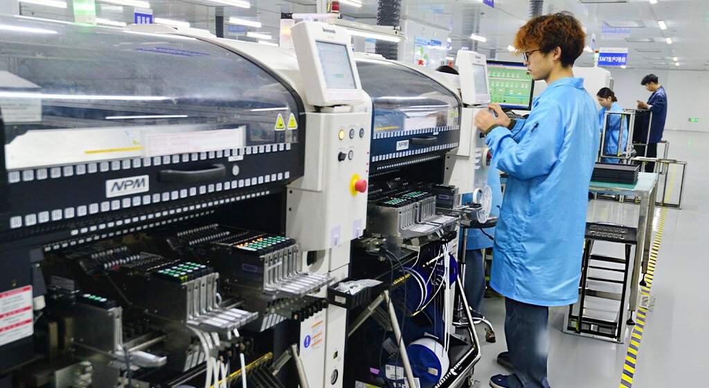
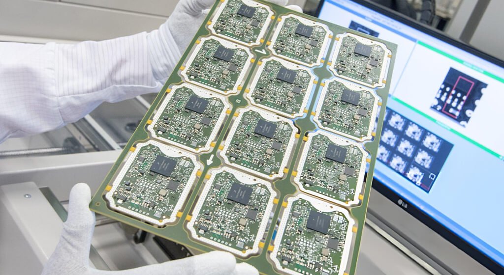
The medical PCB assembly must guarantee that every assembled board meets high-reliability, low-defect, and long-lifecycle performance requirements.
Step 1 — Design for Manufacturability (DFM) & Engineering Review
Before production begins, engineers perform a design validation phase.
Key Checks Include:
- Component Spacing And Placement Feasibility
- Signal Integrity (Especially Analog Medical Signals)
- Thermal Distribution Analysis
- Isolation Between High-Voltage And Low-Voltage Domains
- Risk Analysis (FMEA: Failure Mode And Effects Analysis)
Step 2 — Component Procurement & Traceability Control
Medical PCB assembly requires a controlled and verified supply chain.
Key Requirements:
- Authorized Distributors Only
- Anti-Counterfeit Inspection Procedures
- Lot Number Traceability
- Incoming Quality Inspection (IQC)
Component authenticity is important because counterfeit or degraded components are a major source of field failure in medical electronics.
Step 3 — Solder Paste Printing (Stencil Application)
Solder paste is applied using a precision stainless steel stencil.
Technical Parameters:
- Stencil Accuracy: ±0.003 Mm
- Paste Type: Lead-Free SAC305 Or Equivalent
- Controlled Humidity And Temperature Environment
Solder paste volume variation is one of the most common root causes of SMT defects.
Step 4 — SPI (Solder Paste Inspection)
SPI systems verify:
- Paste Volume Consistency
Alignment Accuracy
Coverage Uniformity
Step 5 — SMT Component Placement (Pick and Place)
Surface Mount Technology (SMT) is the core of modern medical PCB assembly.
Capabilities:
- Component Sizes Down To 0201
- Fine-Pitch BGA Support (0.2 Mm Pitch)
- Placement Accuracy: ±30–50 ΜM
- High-Speed Automated Placement Systems
Step 6 — Reflow Soldering Process
Reflow soldering permanently attaches components using a controlled thermal profile.
Key Stages:
- Preheat
- Thermal Soak
- Reflow Peak
- Cooling Phase
Critical Control Factors:
- Temperature Ramp Rate
- Peak Temperature Stability
- Time Above Liquidus (TAL)
Thermal profile deviation is a leading cause of micro-cracking and solder joint fatigue in medical electronics.
Step 7 — AOI (Automated Optical Inspection)
AOI systems inspect surface-level assembly quality.
Detects:
- Missing Components
- Misalignment
- Solder Bridging
- Polarity Errors
Note: AOI cannot detect hidden solder joint defects under BGAs or QFNs.
Step 8 — Through-Hole Assembly (THT) (If Required)
Some medical devices require mixed technology assembly (SMT + THT).
Used For:
- High-Power Components
- Connectors
- Mechanical Stress Points
Process:
- Manual Or Automated Insertion
- Wave Soldering Or Selective Soldering
Step 9 — X-Ray Inspection (Critical for Medical PCB Assembly)
X-ray inspection is required for hidden solder joints.
Used For:
- BGA Packages
- QFN Components
- Multi-Layer Solder Joints
Detects:
- Voids
- Open Circuits
- Hidden Bridging
X-ray inspection is essential because AOI alone is insufficient for high-density medical PCBs.
Step 10 — Functional Testing (FCT / ICT)
Medical PCBs undergo electrical and functional validation.
Testing Types:
- ICT (In-Circuit Testing)
- Verifies Electrical Connectivity
- Detects Shorts And Opens
FCT (Functional Testing)
- Simulates Real-World Operating Conditions
- Validates System-Level Behavior
Step 11 — Cleaning, Labeling & Traceability Documentation
Final stage includes:
- PCB Cleaning (Flux Residue Removal)
- Serialization (Unique ID Marking)
- Traceability Database Logging
- Inspection Record Archiving
Medical manufacturing requires full lifecycle traceability for audit readiness (FDA / ISO 13485).
Do You Need Any Help?
4. Common Failures in Medical PCB Assemblies (PCBA)
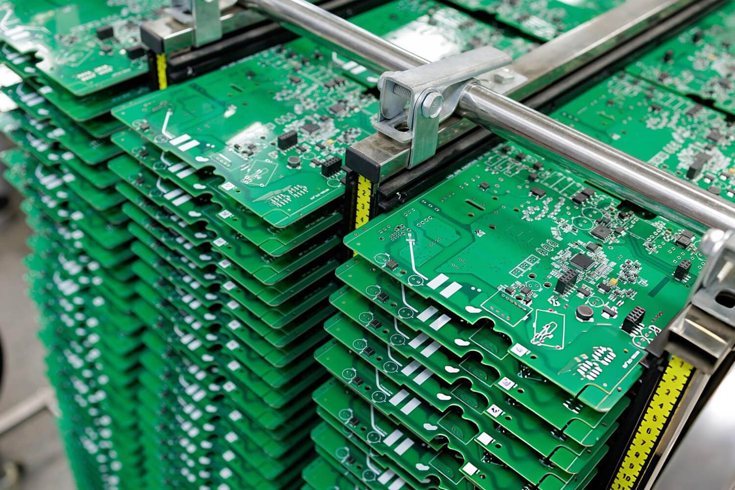
Most failures in medical PCBAs are not random. It often caused by manufacturing variation, thermal stress, or component degradation.
4.1. Solder Joint Failures
Solder joint defects are the most frequent failure mechanism in medical PCB assemblies. Common Types:
Cold Solder Joints
- Poor wetting during reflow
- Insufficient heat or contamination
Solder Fatigue Cracking
- Caused by repeated thermal cycling
- Expansion mismatch between materials
Solder Bridging
- Excess solder paste
- Misaligned components
Thermal expansion mismatch between PCB substrate and components creates mechanical stress over time, especially in 24/7 medical devices.
4.2. Thermal Stress & Cycling Fatigue
Medical devices often operate continuously, creating constant thermal load cycles.
Failure Mechanism:
- Heating during operation
- Cooling during standby cycles
- Repeated expansion/contraction
Affected Components:
- BGAs
- Power ICs
- Connectors
- High-current paths
Thermal cycling is a major driver of micro-crack formation in solder joints, which may not be detectable during initial testing.
4.3. Component Degradation & Aging
Electronic components degrade over time due to:
Electrical Overstress
- Elevated Temperature Operation
- Humidity Exposure
- Voltage Stress
Common Effects:
- Drift In Analog Signal Accuracy
- Increased Leakage Current
- Timing Instability In Digital Circuits
Even small parameter drift can affect diagnostic accuracy in medical instrumentation systems.
4.4. Contamination & Ionic Residue Failure
Solder paste is applied using a precision stainless steel stencil.
Technical Parameters:
- Stencil Accuracy: ±0.003 Mm
- Paste Type: Lead-Free SAC305 Or Equivalent
- Controlled Humidity And Temperature Environment
Solder paste volume variation is one of the most common root causes of SMT defects.
4.5. SMT Process Variation
SMT process instability is a key root cause of PCB failures.
Typical Defects:
- Component Misalignment
- Tombstoning
- Insufficient Solder Paste Volume
- Reflow Profile Inconsistency
Root Causes:
- Stencil Design Errors
- Pick-And-Place Calibration Drift
- Thermal Profile Instability
Small variations in solder paste volume can significantly impact joint reliability at fine-pitch scale.
4.6. BGA & Hidden Joint Failures
Ball Grid Array (BGA) components are widely used in medical devices but difficult to inspect.
Failure Types:
- Voids Under Solder Balls
- Open Circuits
- Hidden Bridging
- Cracked Interconnects
Detection Methods:
- X-Ray Inspection
- Cross-Section Analysis (Failure Analysis Stage)
AOI systems cannot detect internal BGA defects, making X-ray inspection mandatory in high-reliability assemblies.
5. SMT VS THT in Medical PCB Assemblies (PCBA)
In medical PCB assembly, Surface Mount Technology (SMT) and Through-Hole Technology (THT) is a critical engineering decision that directly impacts:
- Device Reliability
- Mechanical Strength
- Signal Integrity
- Manufacturability
- Long-Term Performance
Medical electronics often operate in life-critical environments, meaning the assembly method must balance miniaturization, durability, and regulatory compliance (ISO 13485 / IPC-A-610 Class 3).
Factor | SMT | Through-Hole |
Component Density | Very High | Low–Medium |
Mechanical Strength | Medium | Very High |
Signal Integrity | High | Medium |
Miniaturization | Excellent | Poor |
Automation Level | Fully Automated | Semi-Manual |
Cost Efficiency | High (mass production) | Lower |
Medical Use Case | Wearables, monitors | Power systems, connectors |
6. Medical PCB Design
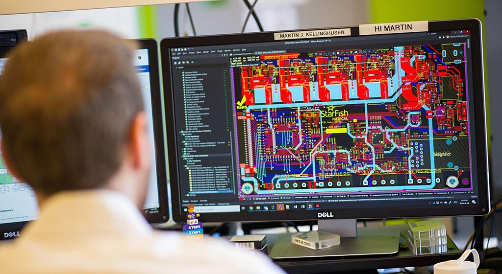
Medical PCB design is a mission-critical engineering that directly determines the reliability, safety, and manufacturability of healthcare electronic systems.
6.1. Signal Integrity in Medical PCB Design
Signal integrity is one of the most critical factors in medical electronics, especially for diagnostic and monitoring systems.
Key Design Considerations:
- Controlled Impedance Routing
- Minimization Of Signal Reflection
- Ground Plane Integrity
- Crosstalk Reduction
Why it matters:
Medical devices often process low-amplitude analog signals, such as:
- ECG Signals
- EEG Signals
- Bio-Sensor Outputs
Even minor noise interference can significantly distort diagnostic accuracy in medical monitoring systems.
6.2. Electrical Isolation & Patient Safety Design
Electrical isolation is mandatory in medical PCB to ensure patient safety.
Design Requirements:
- Isolation between high-voltage and low-voltage domains
- Creepage and clearance distance compliance
- Isolation barriers for patient-connected circuits
- Use of isolation amplifiers or optocouplers
Relevant Standard:
- IEC 60601-1 (Medical Electrical Safety Standard)
Isolation design is directly linked to preventing electrical shock hazards in patient-connected devices.
6.3. EMI/EMC Control in Medical Electronics
Electromagnetic interference (EMI) can degrade performance of sensitive medical systems.
Common Emi Sources:
- Switching Power Supplies
- High-Speed Digital Circuits
- Wireless Communication Modules
Design Techniques:
- Ground Plane Segmentation
- Shielding Techniques
- Decoupling Capacitor Placement
- Controlled Return Paths
Medical PCB design must ensure compliance with IEC 60601-1-2 EMC standards, which define immunity levels for medical equipment.
6. 4. Thermal Management in Medical PCB Design
Thermal stability is essential for long-term reliability.
Key Considerations:
- Power Dissipation Distribution
- Thermal Via Placement
- Copper Pour Optimization
- Heat Sink Integration
Failure Mechanism:
- Thermal Cycling Causes Solder Joint Fatigue
- Localized Overheating Accelerates Component Aging
Thermal imbalance is a leading contributor to long-term failure in continuously operating medical devices.
6. 5. Component Selection & Derating Strategy
Medical PCB design requires conservative component usage.
Design Rules:
- Use Components Below Maximum Rated Stress (Derating)
- Prefer High-Reliability-Grade Components
- Avoid Marginal Tolerance Components
- Ensure Long Lifecycle Availability (10+ Years)
Component derating significantly improves long-term system reliability under continuous operation.
7. Conclusion
As medical electronics evolve toward AI-assisted diagnostics, wearable health monitoring, and fully connected IoT healthcare ecosystems, Medical PCB assembly is becoming more compact, more data-intensive, and more reliability-critical.
At the same time, regulatory scrutiny and cybersecurity requirements are increasing.
Manufacturers that can integrate precision SMT production with robust quality systems and full regulatory traceability will define the next generation of medical electronics manufacturing.