The global flexible electronics market grows rapidly. Multiple industry reports estimate the market could exceed $50 billion before 2030.
Flexible printed circuit boards are now important in global flexible electronics. When we choose Flex PCB materials, we should consider its reliability, bending life, thermal stability, and manufacturing cost.
This guide explains everything about flex PCB materials. It also helps you find a right material for your Flex PCB project.
Table of Contents
1. What Are the Main Materials Used in Flex PCBs?
The main flex PCB materials are polyimide (PI), polyester (PET), liquid crystal polymer (LCP), and PTFE-based laminates.
Each material serves different electrical, thermal, and mechanical requirements.
Common Material Stack Components:
Layer | Typical Material |
Base Film | Polyimide Or PET |
Copper Foil | Rolled Annealed Copper |
Adhesive | Acrylic Or Epoxy |
Coverlay | Polyimide Coverlay |
Stiffener | FR4, PI, Stainless Steel |
1.1. Polyimide (PI)

Polyimide is the main base material in flexible circuits. It is excellent flexibility and strong thermal resistance.
Most high-reliability flex PCBs use polyimide films because they withstand:
- High Soldering Temperatures
- Repeated Bending Cycles
- Harsh Chemical Environments
- Wide Operating Temperature Ranges
Typical Properties:
Property | Polyimide |
Continuous Temperature | Up to 200–260°C |
Flexibility | Excellent |
Moisture Resistance | Moderate |
Cost | Medium to high |
- Popular commercial materials is Kapton and Apical films.
1.2. PET (Polyester)

PET is cheaper than polyimide and widely used in cost-sensitive products. It works well in applications with limited thermal stress and minimal repeated bending.
Advantages | Disadvantages |
Low Cost | Lower Heat Resistance |
Good Dimensional Stability | Reduced Chemical Durability |
Easy Mass Production | Poor High-Temperature Solder Performance |
1.3. Copper Foil

Copper forms the electrical traces inside a flex PCB. Two major copper types are used:
Rolled Annealed Copper
- RA copper is preferred for dynamic flex applications. It performs better under repeated bending because its grain structure is more ductile.
Electro-Deposited Copper
- ED copper costs less and works well in static flex designs. Static flex circuits bend only during installation.
1.4. Adhesives

Adhesives bond copper foil to the flexible substrate. Common adhesive types include:
- Acrylic
- Epoxy
These materials affect thermal performance and flexibility.
Adhesive thickness directly affects flexibility and reliability.
Typical Adhesive Thicknesses
Thickness | Use |
12.5 μm | Ultra-Thin Flex |
25 μm | Standard Flex Circuits |
50 μm | Heavy-Duty Bonding |
1.5. Coverlay

Coverlay is a protective film laminated onto flexible printed circuits. It protects exposed copper traces from moisture, oxidation, mechanical damage, and electrical short circuits.
Coverlay is made of Polyimide Film and Adhesive Layer.
Coverlay Thickness Affects Flexibility, Protection, And Manufacturability.
Typical Coverlay Film Thicknesses:
Thickness | Application |
12.5μm | Ultra-Flexible Circuits |
25μm | Standard Flex PCBs |
50μm | Heavy-Duty Protection |
1.6. Stiffener

A stiffener is a rigid or semi-rigid material bonded to selected areas of a flex PCB.
Stiffeners in flex PCB do not carry electrical signals. Their primary role is mechanical reinforcement.
Stiffeners Are Commonly Added Beneath:
- Connectors
- IC Components
- BGA Regions
- Switch Contacts
- Mounting Points
These reinforced areas improve structural support during assembly and product operation.
Proper thickness is critical. Excessively thick stiffeners may increase stress concentration near transition regions.
Typical Thickness:
Application | Thickness |
ZIF Connector Support | 0.2–0.3 mm |
Heavy SMT Assembly | 0.3–0.5 mm |
Ultra-Thin Wearables | 0.05–0.1 mm |
Designers should balance rigidity with overall flex performance.
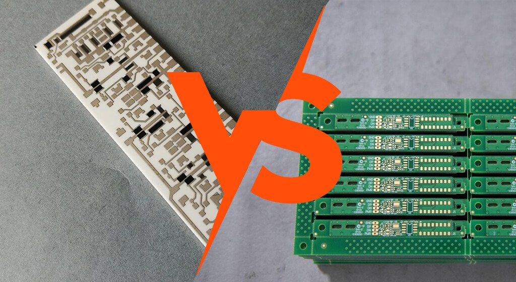
2. Polyimide vs PET: Which Flex PCB Material Is Better?

Polyimide is better for high-performance electronics. PET is better for low-cost consumer products with limited thermal exposure.
Comparison:
Property | Polyimide | PET |
Max Operating Temperature | ~260°C | ~120°C |
Dynamic Flex Performance | Excellent | Limited |
Cost | Higher | Lower |
Moisture Absorption | Moderate | Lower |
SMT Compatibility | Excellent | Poor |
Dimensional Stability | Good | Moderate |
Work Well In |
|
|

Do You Need Any Help?
3. What Is the Best Flex PCB Material for Dynamic Bending?
Dynamic flex applications require materials that survive continuous mechanical stress. Rolled annealed copper with polyimide is the preferred group.
Dynamic bending differs from static flexing. Static flex bends only during installation. Dynamic flex bends repeatedly throughout product life.
The main issue is copper fatigue cracking. Rolled annealed copper performs much better than electrodeposited copper because of its grain structure.

Recommended Design Rules:
Design Parameter | Recommended Practice |
Copper Type | Rolled Annealed |
Bend Radius | ≥10× Thickness |
Trace Direction | Perpendicular to Bend |
Via Placement | Avoid Bend Zones |
Layer Count | Minimize in Flex Region |
IPC-2223 provides design guidance for flexible printed boards. Many PCB Fabrication failures result from violating bend radius recommendations.
Engineers should always discuss bend cycle requirements with fabricators during DFM review.
4. Why Does Moisture Absorption Cause Flex PCB Failures?

Polyimide absorbs more moisture than FR4. This creates assembly and reliability risks if storage conditions are poorly controlled.
Moisture Absorption Values:
Material | Moisture Absorption |
Polyimide | 1.5–3% |
PET | 0.2–0.8% |
LCP | <0.04% |
PTFE | <0.02% |
Moisture Absorption Cause:
- Delamination
- Blistering
- Solder Voiding
- Popcorning
- Impedance Drift
During lead-free reflow, trapped moisture expands rapidly. This internal vapor pressure damages laminate interfaces.
Most PCB assemblers bake flex circuits before assembly. Common bake conditions range from 105°C to 125°C for several hours.
Moisture Problems Worsen In:
- Thick Multilayer Flex
- Rigid-Flex Designs
- Humid Storage Environments
LCP materials absorb substantially less moisture than PI. That’s why RF engineers increasingly adopt LCP for mmWave antennas.
Proper packaging is essential. Vacuum-sealed moisture barrier bags reduce absorption during storage and transport.
5. Why Is LCP Becoming Popular in RF Flex PCB Design?

Liquid crystal polymer offers extremely low dielectric loss and very low moisture absorption. These properties make it ideal for RF and mmWave systems.
5G antennas, phased arrays, and radar modules increasingly use LCP-based flex circuits.
LCP Electrical Properties
Property | LCP | Polyimide |
Dk | ~2.9–3.2 | ~3.4–3.6 |
Df | Very Low | Moderate |
Moisture Absorption | Extremely Low | Moderate |
RF Stability | Excellent | Good |
LCP Provides:
- Stable Impedance
- Reduced Insertion Loss
- Improved Antenna Efficiency
- Better Environmental Stability
The primary disadvantage is cost. LCP laminates is substantially more expensive than standard PI materials.
Manufacturing complexity also increases because fewer fabricators specialize in LCP processing.
Still, RF engineers increasingly view LCP as the preferred substrate for frequencies above 24 GHz.
Do You Need Any Help?
6. What Is the Best Flex PCB Material for High Temperatures?

Polyimide is the industry standard for high-temperature flex circuits. However, specialty applications may require advanced materials.
Standard PI Survives:
- SMT Reflow
- automotive Thermal Cycling
- Industrial Electronics Environments
Temperature Capabilities:
Material | Continuous Operating Temp |
PET | ~105–120°C |
PI | ~200–260°C |
PEEK | ~250°C |
PTFE | ~260°C |
PET generally cannot tolerate lead-free reflow temperatures.
For extreme thermal environments, engineers may consider:
- PEEK
- PTFE Composites
- Ceramic-based Flexible Structures
Material Selection Depends On:
- Peak Operating Temperature
- Thermal Cycling Frequency
- Mechanical Flex Requirements
- Chemical Exposure
Automotive under-hood electronics often require temperatures above 150°C. Aerospace systems may face even harsher environments.
Engineers Should Evaluate:
- Tg
- Td
- CTE
- Long-term Thermal Aging Data
Short-term temperature ratings alone are insufficient for reliability analysis.
7. How Do Flex PCB Materials Affect Signal Integrity?
Flex PCB Material dielectric properties strongly influence high-speed performance. As data rates increase, material losses become more critical.
Important Electrical Parameters Include:
- Dielectric Constant (Dk)
- Dissipation Factor (Df)
- Conductor Roughness
- Moisture Stability.
Higher Df values increase insertion loss. It becomes significant above several GHz.

Polyimide performs adequately for many digital systems. However, LCP and PTFE outperform PI in high-frequency RF applications.
Engineers must carefully model material behavior when you are designing:
- USB4,
- PCIe,
- mmWave Antennas,
- Radar Modules,
- RF Transceivers
Impedance control becomes more difficult in flex circuits because material thickness tolerances vary more than rigid laminates.
Copper roughness also contributes significantly to conductor loss at high frequencies.
8. Which Flex PCB Materials Work Best for Medical Devices?

Medical electronics require materials with proven reliability, biocompatibility, and sterilization compatibility.
Polyimide Is Widely Used Because Of Flexibility, Thermal Endurance, and Long-Term Reliability.
Medical Flex PCB Applications:
- ECG Patches
- Wearable Monitors
- Implantable Sensors
- Catheter Electronics
Engineers Must Consider:
- ISO 10993 Requirements
- Sterilization Compatibility
- Chemical Resistance
- Long-Term Flex Fatigue
LCP is increasingly attractive for implantable RF devices because of its low moisture absorption.
Medical OEMs often require extensive material traceability and reliability qualification before approval.
Dynamic flex life becomes especially important in wearable medical systems subjected to constant body movement.
9. How Should PCB Engineers Select Flex PCB Materials?
PCB engineers should select flex PCB materials based on mechanical stress, thermal environment, electrical performance, assembly requirements, and long-term reliability targets.
According to IPC Association Connecting Electronics Industries, flexible circuit reliability depends heavily on proper material selection and stackup engineering.

9.1. What Factors Should PCB Engineers Evaluate First?
The most important first step is defining the application environment.
Key Evaluation Factors:
Design Requirement | Why It Matters |
Bend Cycles | Determines flex fatigue life |
Operating Temperature | Determines substrate survivability |
Signal Frequency | Determines dielectric requirements |
Product Thickness | Determines material thickness limits |
Assembly Process | Determines thermal resistance needs |
Environmental Exposure | Determines moisture resistance |
Designers should separatestatic flex applications, and dynamic flex applications.
Static flex bends only during installation. Dynamic flex bends repeatedly during operation.
This distinction changes both substrate and copper selection.
9.2. How Does Bend Frequency Affect Material Selection?
Mechanical bending is usually the most critical design factor. Dynamic flex applications require high ductility, low stress concentration, and fatigue-resistant copper.
The Preferred Material Combination Is:
- Polyimide Substrate,
- Rolled Annealed (RA) Copper,
- Adhesiveless Laminate.
IPC-2223 recommends larger bend radii for repeated-flex applications.
Recommended Flex Guidelines:
Flex Type | Recommended Bend Radius |
Static flex | ≥6× thickness |
Dynamic flex | ≥10× thickness |
Applications Requiring Dynamic Flex Include:
- Robotics
- Foldable Electronics
- Printer Heads
- Wearable Devices
Engineers Should Avoid Vias In Bend Zones, Sharp Trace Corners, and Thick Copper In Flex Areas
9.3. How Should Engineers Select Copper for Flex PCBs?
Copper selection is critical for flex reliability.The Two Main Copper Types Are:
- Rolled Annealed (RA)
- Electrodeposited (ED)
RA copper is preferred for dynamic flex because it offers better ductility.
Property | RA Copper | ED Copper |
Flexibility | Excellent | Moderate |
Fatigue Resistance | High | Lower |
Cost | Higher | Lower |
Grain Structure | Horizontal | Vertical |
Typical Recommendations:
Application | Recommended Copper |
Dynamic Flex | RA Copper |
Static Flex | ED Or RA |
Ultra-Thin Wearable | Thin RA Copper |
Low-Cost Electronics | ED Copper |
Thinner copper improves flexibility but reduces current-carrying capacity.
9.4. How Should Engineers Evaluate Thickness Requirements?
Thickness Strongly Affects:
- Flexibility
- Bend Radius
- Mechanical Durability
- Packaging Density
Ultra-thin constructions improve flexibility but reduce handling robustness.
Typical Thickness Ranges:
Flex Type | Total Thickness |
Standard flex | 75–200µm |
Ultra-thin flex | 25–75µm |
Advanced wearable flex | <25µm |
10. Final Thoughts
Flex PCB materials directly determine electrical performance, mechanical reliability, manufacturing yield, and product lifetime.
Polyimide is a widely used flexible substrate because it balances thermal resistance, flexibility, and manufacturability.
However, newer materials like LCP is increasingly used in high-frequency applications.
The most successful PCB engineers optimize materials around:
- Application Physics
- Mechanical Stress
- RF Behavior
- Assembly Constraints
- Long-Term Reliability
As electronics become thinner, faster, and more flexible, material engineering becomes even more important than layout complexity.
Get a PCB Quote