Modern drones depend on a single critical component. That component is the flight controller PCB.
The flight controller acts as the drone’s brain. It processes sensor data. It calculates orientation. It controls motor outputs. It maintains stable flight.
According to the Federal Aviation Administration, commercial drone operations continue to grow worldwide. The global UAV market is expected to exceed tens of billions of dollars this decade. As drone applications expand, demand for reliable flight controller PCBs also increases.
A well-designed flight controller PCB improves stability, reduces noise, enhances safety, and extends system reliability. Poor PCB design can cause crashes, unstable flight behavior, and sensor failures.
This guide explains flight controller PCB architecture, design practices, component selection, manufacturing considerations, and troubleshooting methods.
Table of Contents
1. What Is a Flight Controller PCB?

A flight controller PCB is the central electronic board inside a drone.
It receives information from multiple sensors. It then calculates the aircraft’s position and orientation. Based on these calculations, it sends commands to electronic speed controllers (ESCs).
A typical flight controller performs thousands of calculations every second.
The PCB integrates processing, sensing, communication, and power management functions. Modern flight controllers combine these features into compact multilayer circuit boards.
Without a flight controller PCB, autonomous or stabilized flight would be impossible.
2. How a Flight Controller Works?

The flight controller continuously monitors aircraft motion.
Sensors measure angular velocity, acceleration, altitude, heading, and position. The onboard processor compares actual movement with desired movement.
Control algorithms generate correction signals. These signals adjust motor speed through ESC outputs.
The process repeats hundreds or thousands of times per second.
This closed-loop feedback system allows drones to maintain stability during wind disturbances, payload changes, and aggressive maneuvers.
Fast processing and accurate sensor readings are essential for successful operation.

Do You Need Any Help?
3. Main Components Found on Flight Controller PCBs

Every flight controller PCB contains several essential components. These components work together to maintain stable flight.
Typical Assemblies Include:
- Microcontroller (MCU)
- Inertial Measurement Unit (IMU)
- Voltage Regulators
- Barometer
- Magnetometer
- GPS Interface
- Communication Ports
- Flash Memory
- Oscillators
- Filtering Circuits
Component selection directly affects flight performance, reliability, and manufacturing cost.
4. Microcontroller Architectures: STM32, ESP32, and Firmware Targets

The microcontroller unit (MCU) serves as the computational core.
Most modern flight controllers use STM32 processors. These devices provide high processing power and low energy consumption.
Flight Controller Hardware Stack | |
Firmware Layer | Betaflight / ArduPilot / iNav |
Processing Layer | STM32H7 (480MHz) / STM32F7 / ESP32 |
Sensor Bus | SPI @ 24MHz / I2C Bus |
Hardware Layer | ICM-42688-P IMU / SPL06 Barometer |
4.1. MCU Generation Performance Comparisons
The STM32 series from STMicroelectronics remains the undisputed industry standard for open-source drone firmware.
Popular Option Include:
- STM32F405
- STM32F411
- STM32F722
- STM32H743
Legacy STM32F4 chips are fading due to flash memory limitations and slower processing loops.
Modern drone firmware packages like Betaflight and ArduPilot demand significant processing headroom. Modern drone builds heavily favor the STM32F722 and the high-performance STM32H743 microcontrollers.
According to STMicroelectronics datasheets, the STM32H743 runs at clock speeds up to 480 MHz. It features a hardware Floating Point Unit (FPU) to execute complex proportional-integral-derivative (PID) loop calculations.
The STM32F722 operates at 216 MHz. It can offer an excellent balance of cost and performance. It remains highly popular for standard FPV (First-Person View) racing drones and freestyle quadcopters.
4.2. The Rise of ESP32 and Open-Source Ecosystems
Engineers frequently ask if the low-cost ESP32 chip can run advanced flight firmware. The ESP32 offers built-in Wi-Fi and Bluetooth capabilities at a very low price point.
However, compiling Betaflight for custom ESP32 hardware layouts introduces serious firmware compilation and timer mapping hurdles. The ESP32 architecture lacks the native nested vectored interrupt controllers found in ARM Cortex-M cores.
This architectural difference makes precise, deterministic motor PWM (Pulse Width Modulation) generation much more difficult. For industrial UAV stability, stick to ARM-based STM32 chips with established firmware target configurations.
Do You Need Any Help?
5. Sensor Integration and Signal Integrity: Gyros and Barometers

A flight controller is only as stable as the real-time kinematic data it collects. Inertial Measurement Units (IMUs) measure rapid rotational and translational forces during dynamic flight conditions.
Critical Sensor Isolation Zones | ||
HIGH-NOISE ZONE | ISOLATION | SENSITIVE ZONE |
Brushless ESC Pads ====> | Keep Traces ===> | ICM-42688-P |
Switches & Motors ====> (High Current) | Over 10 mm ===> Separation | MEMS Gyro(Solid Ground)
|
5.1. Gyroscope Selection and SPI Speed Constraints
The TDK InvenSense ICM-42688-P has widely replaced legacy gyroscopes like the MPU6000 on modern PCBs.
However, this precision comes with an engineering tradeoff: high sensitivity to mechanical vibration. Some users often report dropped data frames when clocking the sensor via the Serial Peripheral Interface (SPI).
The ICM-42688-P supports SPI speeds up to 24 MHz, but long PCB traces degrade signal edge transitions. Keep the SPI traces between your MCU and your IMU under 10 mm in total length.
Ensure your high-speed SPI trace layout maintains a strict, calculated 50-ohm characteristic trace impedance. This matching eliminates problematic signal reflections that trigger fatal control loop processing errors mid-flight.
5.2. Mechanical Isolation and Barometer Airflow Controls
Barometric pressure sensors, such as the Infineon SPL06, are critical for autonomous altitude hold functions. Airflow currents generated by spinning drone propellers create extreme localized pressure changes and turbulent air zones.
Never place a sensitive MEMS barometer directly in line with high-speed open air paths. Protect the chip by positioning it on the protected bottom layer of your multi-layer PCB assembly.
Engineers routinely place a small piece of open-cell black foam directly over the top of the barometer. This foam blocks intense ambient sunlight and pressure waves while allowing true static ambient air pressure readings.
6. Power Distribution and Noise Mitigation: The 6S LiPo Challenge
Modern drones utilize high-voltage Lithium Polymer (LiPo) battery packs that present severe electrical challenges. Power distribution networks on an FC must withstand extreme electrical noise generated by rapid motor braking.

6.1. Mitigating High-Voltage Inductive Voltage Spikes
A fully charged 6S LiPo battery supplies 25.2 volts directly to the drone power system. When brushless motors brake hard, they generate inductive voltage spikes exceeding double the nominal input battery voltage.
These massive voltage surges can easily destroy fragile internal 5V switching buck regulators. Always place a low-ESR (Equivalent Series Resistance) electrolytic capacitor across your main battery landing pads.
A 35V, 470μF or 680μF solid capacitor filters out destructive high-voltage spikes effectively. It can protect down-regulated power rails from voltage breakdown events during aggressive full-throttle maneuvers.
6.2. Designing Low-Noise Multi-Stage Voltage Regulators
A single voltage regulator cannot cleanly step down high-voltage LiPo power straight to sensitive 3.3V microcontrollers. Switching buck regulators provide great power efficiency but introduce significant high-frequency ripple into the system.
Implement a multi-stage power cascade layout to guarantee completely clean power for your flight components.
First, use an efficient switching regulator to step the raw input battery voltage down to 5 volts.
Next, pass that 5V line through a high Power Supply Rejection Ratio (PSRR) Linear Regulator (LDO). The LDO drops the voltage down to a stable 3.3V rail to feed your sensors.
Design Note: Place small 0.1μF and 10μF ceramic decoupling capacitors as close to the MCU power pins as physically possible.
Do You Need Any Help?
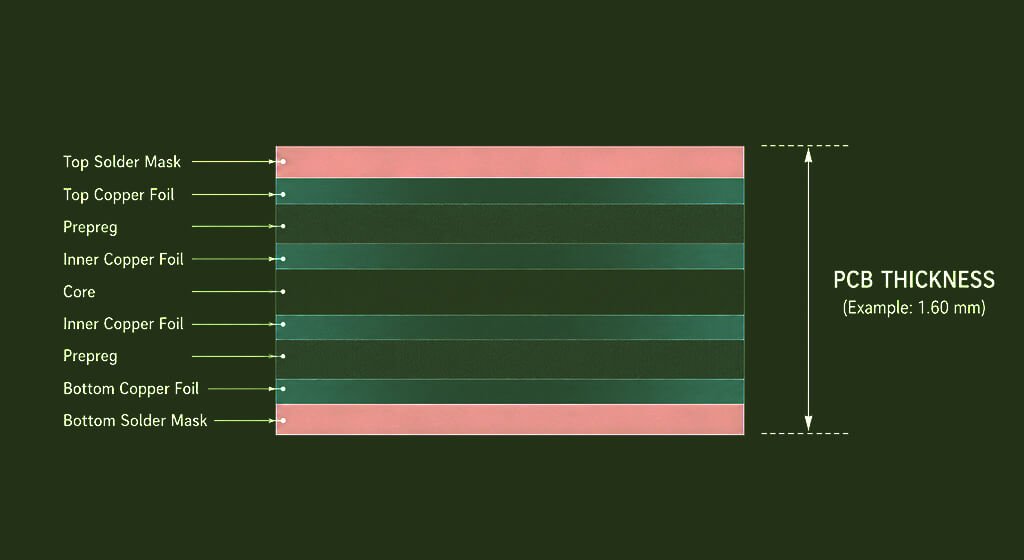
7. Multi-Layer PCB Stackup and Advanced EMI Shielding
A poorly planned PCB layer stackup is a leading cause of electromagnetic interference (EMI) failures. High-current motor power rails must coexist alongside delicate, high-frequency digital and analog sensor lines.

7.1. Maximizing Performance with a 4-Layer Layout
Never design a modern flight controller on a cheap, basic two-layer printed circuit board layout. Two-layer boards do not offer the structural shielding needed to isolate high-speed flight return current loops.
A standard 4-layer PCB layout is the minimum requirement for a reliable drone flight controller. This structured configuration provides designated, separate layers for routing high-speed signals, clean power, and ground returns.
According to Altium design specifications, close coupling between signal and ground layers prevents electromagnetic fields from spreading. This intentional structural layout effectively eliminates problematic internal crosstalk across your multi-layer PCB assembly.
7.2. Advanced Ground Plane Strategies for Mixed-Signal Isolation
For modern high-speed flight controllers, a unified, solid ground plane yields much better results.
Do not cross sensitive digital traces over gaps or splits in your underlying reference ground plane. Crossing a split ground plane forces return currents to take long, looping structural paths.
These long return loops turn regular copper traces into highly inefficient, radiating loop antennas. Keep the copper ground plane completely solid under all high-frequency SPI, UART, and I2C lines.
8. Reducing EMI in Flight Controller PCBs

Electromagnetic interference is a common design challenge.
Flight controllers operate near motors, ESCs, radios, and power systems.
Each source generates electrical noise.
Common EMI Reduction Strategies Include:
- Short Signal Traces
- Solid Ground Planes
- Proper Filtering
- Shielding Techniques
- Differential Routing
Noise mitigation should begin during PCB layout.
Attempting corrections after fabrication is often costly.
Preventive design practices produce better results.
9. Trace Routing Guidelines

Trace routing influences overall system performance.
Critical signals require careful attention.
Design Recommendations
- Keep Traces Short
- Avoid Unnecessary Vias
- Minimize Sharp Corners
- Separate Analog And Digital Signals
- Route Clocks Carefully
High-current motor paths should remain isolated from sensitive sensor traces.
This reduces coupling effects.
Proper routing improves both functionality and manufacturability.
Do You Need Any Help?
10. High-Speed Communication Interfaces
Modern flight controllers rely on multiple communication buses.
Common Interfaces Include:
- SPI
- I2C
- UART
- CAN
- USB
SPI is frequently used for IMU communication.
It offers higher speed and lower latency.
I2C remains popular for auxiliary sensors.
However, it is generally more susceptible to electrical noise.
Interface selection affects performance and PCB layout complexity.
11. ESC Communication Technologies
Electronic speed controllers receive commands from the flight controller. Older systems used PWM signals. Modern drones increasingly use digital protocols.
Popular Options:
- Oneshot
- Multishot
- Dshot150
- Dshot300
- Dshot600
DShot protocols improve reliability.
Digital communication reduces timing errors and calibration requirements. This contributes to more predictable flight performance.
12. GPS Integration Challenges
GPS enables navigation and autonomous flight. However, integrating GPS requires careful design.
RF signals are extremely weak.
Noise from switching regulators can degrade reception quality.
Engineers typically separate GPS modules from noisy circuits.
Grounding and filtering techniques also improve performance.
Reliable GPS operation depends on both hardware and layout quality.
Do You Need Any Help?
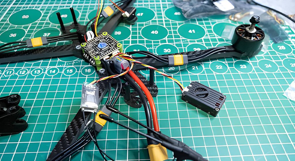
13. Physical Layout and Thermal Management: All-in-One Stacks
All-in-One (AIO) flight boards combine the flight controller and electronic speed controllers onto one miniature PCB. These compact designs face intense space limitations and extreme thermal stresses during high-current operations.

13.1. Geometric Sensor Placement Tactics
Mechanical motor vibrations travel directly through the rigid carbon fiber frame of your drone chassis. These continuous physical vibrations can completely saturate the sensitive onboard MEMS gyroscope control loops.
Always mount your IMU chip at the exact geometric center of your flight controller board. Positioning the sensor at the center minimizes unwanted rotational acceleration forces acting on the gyro.
Maintain a strict 3-to-1 distance rule to separate sensitive analog signals from digital noise. Keep all high-frequency lines isolated from low-noise traces by three times the width of the trace.
13.2. Mitigating Thermal Throttling in High-Density AIO Boards
High-performance MOSFETs (Metal-Oxide-Semiconductor Field-Effect Transistors) on an ESC generate considerable thermal energy under load. Temperatures on compact AIO boards can easily climb well above 100 degrees Celsius during flight.
This extreme localized heat conducts through internal copper layers and can cause severe MCU thermal throttling. To prevent this, place thermal isolation slots in the copper layers between power and logic zones.

Utilize heavy 2-ounce or 3-ounce copper sheets for all high-current power distribution pathways. Thicker copper significantly reduces electrical resistance and spreads heat evenly across the surface of the board.
Incorporate numerous thermal vias into your design to vent heat to outer layers for dissipation. Adequate thermal management ensures your internal logic components operate safely within stable, predictable temperature ranges.
14. Manufacturing, DFM, and Real-World Field Validation
Design for Manufacturability (DFM) rules ensure your custom flight controller can be reliably mass-produced. Ignoring mechanical constraints often results in non-functional prototypes and short circuits during assembly.

14.1. Manufacturing, DFM, and Real-World Field Validation
Standard drone stacks utilize M2 or M3 metal screws to secure the electronic hardware layers together.
As nylon or steel hardware is tightened down, it creates intense mechanical pressure around the hole. This mechanical friction can scratch off thin solder mask insulation over time, exposing raw copper underneath.
If a high-voltage power trace runs near that mounting hole, the screw can create a short circuit. Keep all copper traces at least 1.0 mm away from outer mounting hole edges.
14.2. Implementing Safety Diodes for Safe USB Configuration
Flight controllers require two separate power injection inputs: battery power (VBAT) and 5V USB power. Connecting both power sources simultaneously during computer firmware tuning is a highly common field scenario.
Without proper circuit protection, the high-voltage battery rail can back-feed power straight into your computer. This high-voltage back-feeding can permanently destroy the delicate USB ports on an expensive laptop.

Place low-forward-voltage Schottky diodes on both the USB 5V and regulator 5V lines. This simple dual-diode ORing configuration blocks reverse current paths, keeping your programming hardware safe.
Do You Need Any Help?
15. Comparative Technical Architecture Analysis
To wrap up these design concepts, this master technical reference table outlines clear engineering choices.
These parameters differentiate a basic, entry-level flight controller from an industrial-grade, highly reliable autonomous guidance system.
Engineering Parameter | Hobby-Grade FPV Controller | Industrial-Grade UAV Autopilot |
Microcontroller (MCU) | STM32F722 or STM32F405 | STM32H743 Dual-Core ARM Cortex |
IMU Sensors Used | Single ICM-42688-P | Dual Redundant IMUs (ICM-42688-P + BMI270) |
PCB Layer Count | 4-Layer standard stackup | 6-Layer to 8-Layer High-Density HDI |
Copper Weight (Power) | 1.0 oz ft^2 standard copper | 2.0 to 3.0 oz ft^2 heavy copper |
Voltage Filtering | Single external electrolytic capacitor | Onboard multi-stage LC low-pass filters |
Barometer Protection | Open exposed PCB surface placement | Dedicated bottom-layer routing with foam shielding |
Power Inputs | Unprotected single buck regulator | Dual-redundant power inputs with ideal diodes |
16. Conclusion
The flight controller PCB remains the foundation of every modern drone. Its design directly influences stability, safety, responsiveness, and reliability.
Successful flight controllers combine robust hardware with optimized firmware.
Engineers must carefully consider sensor selection, power management, PCB layout, EMI control, and manufacturing quality.
Get a PCB Quote