/For Leaded Components/
Through-Hole PCB Assembly
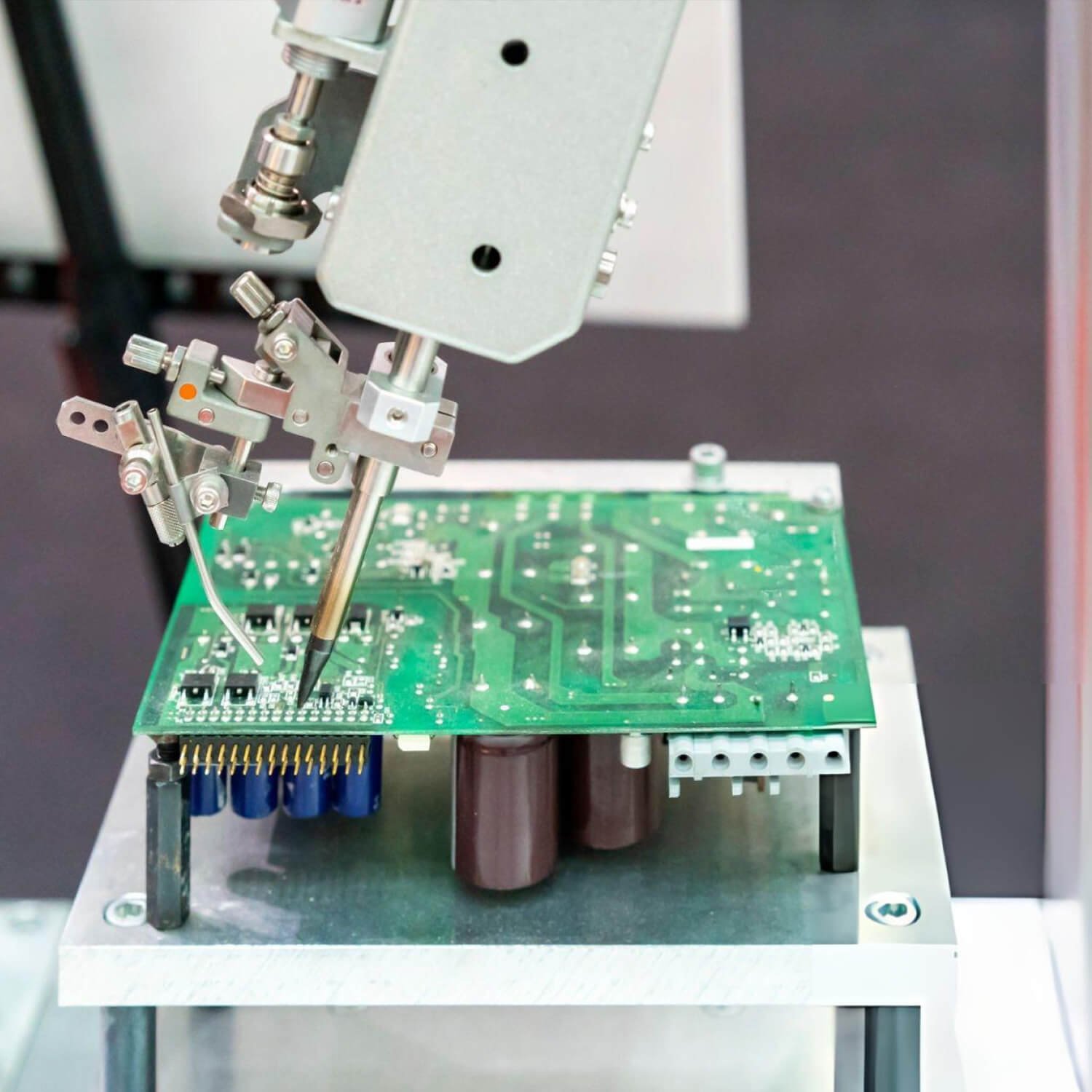
PCBSAIL provides through-hole PCB assembly for engineering prototypes, pilot builds, and repeat production. We coordinate leaded-component insertion, soldering, mixed SMT and THT process planning, sourcing, inspection, testing, and final delivery according to the approved build package.
Our THT (Through-Hole Technology) assembly solutions are widely used in industry, where circuits must withstand vibration, thermal stress, high voltage, and harsh environmental conditions.
Through-hole and mixed SMT + THT assembly support
Manual, wave, and selective soldering routes selected by project
Inspection and testing defined by design risk.
Full-turnkey, partial-turnkey, and consigned material options
What Is Through-Hole PCB Assembly?
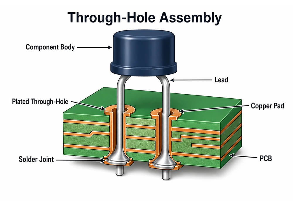
Through-hole PCB assembly mounts components by inserting their leads through plated holes in a pcb board. The leads are soldered or connected on the opposite side. It is commonly used for transformers, relays, switches, and other parts that need leaded packaging or additional mechanical support.
THT does not simply replace surface-mount technology. SMT was commonly used for compact control circuitry and THT for power, connection, or electromechanical components.
We deliver high-quality PCB assembly solutions with experienced engineering teams and advanced equipment.
Choosing the Right PCB Assembly Process
The appropriate assembly depends on component types, PCB layout, mechanical requirements, and manufacturing goals. In many projects, a combination of SMT and through-hole assembly provides the best balance of performance, reliability, and production efficiency.

Through-Hole Assembly
THT is commonly used for connectors, terminals, transformers, relays, large capacitors, and other components exposed to mechanical stress. Engineering should verify lead compatibility, plated hole dimensions, solder accessibility, thermal mass, and inspection requirements.
Surface Mount Technology
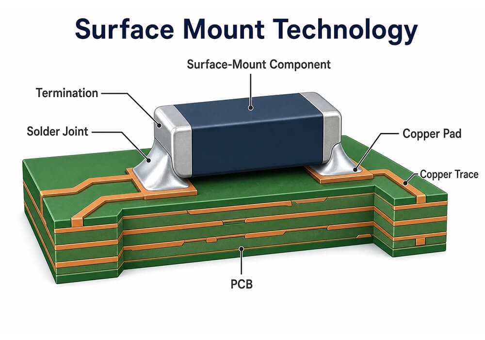
SMT is the preferred choice for compact PCB layouts, fine-pitch components, and double-sided assemblies. Successful SMT production depends on component placement accuracy, stencil design, reflow soldering, inspection strategy, and rework accessibility.
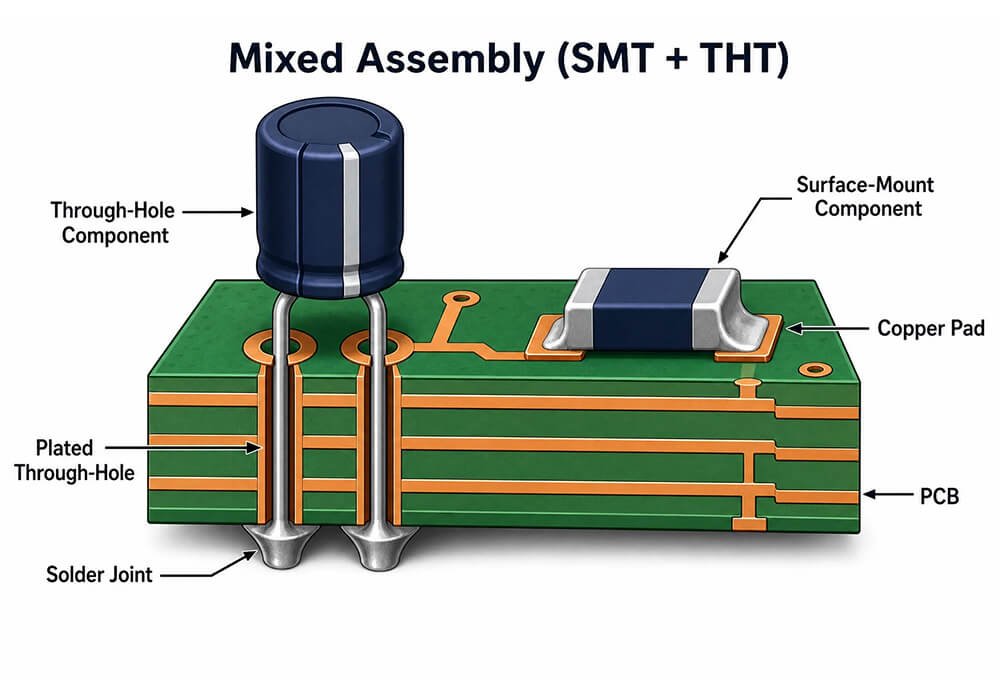
Mixed
Mixed SMT and THT Assembly combines both technologies on a single PCB. This approach is often used when SMT handles control circuitry while through-hole components provide robust power or interface connections.
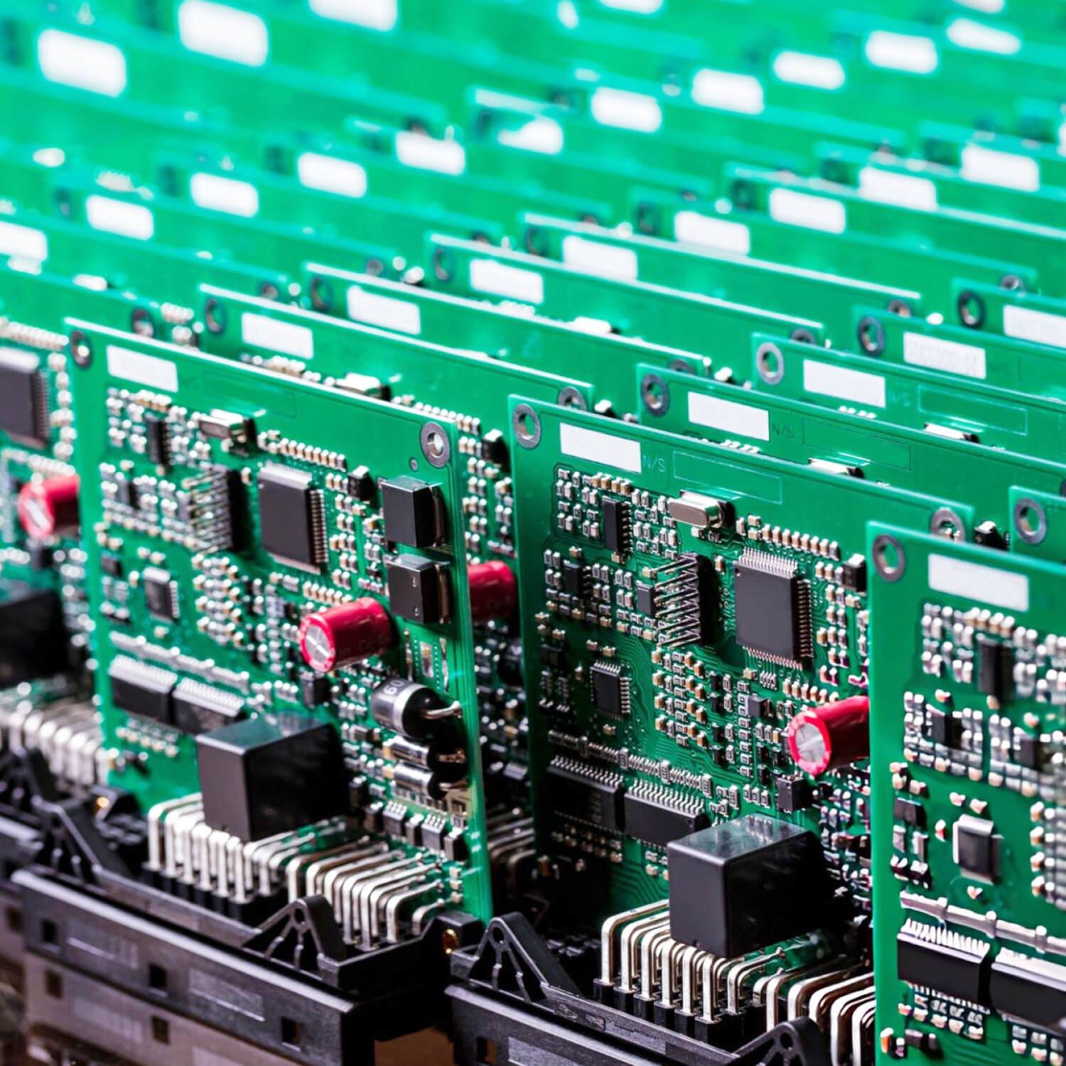
Our SMT Assembly Capability
We supports leaded-component assembly as a standalone service or as part of a mixed-technology PCBA project.
Supported Component Types | Axial and radial components, connectors, terminals, switches, relays, transformers, large capacitors, inductors, and other leaded components |
Component Insertion | Manual insertion, lead forming, and project-specific component preparation |
Soldering Processes | Hand soldering, wave soldering, selective soldering, or combined soldering based on product requirements |
Mixed Technology Assembly | Integrated SMT and through-hole assembly with coordinated production planning |
Inspection & Testing | Visual inspection, AOI, X-ray inspection, Flying Probe Test, ICT, FCT, and customer-defined testing |
Material Supply Options | Full Turnkey, Partial Turnkey (Hybrid), and Consigned PCB Assembly |
Production Capability | Engineering prototypes, NPI builds, pilot production, low-volume manufacturing, and high-volume production |
What Should You Send?
- 1. Gerber or ODB++ fabrication files
- 2. Bill of materials with manufacturer details
- 3. Centroid or component placement data
- 4. Assembly drawings and special instructions
- 5. Testing, programming, and packaging requirements
Wave, Selective, and Press-Fit Options
The most suitable through-hole assembly method depends on the PCB design, component types, production volume, and reliability requirements.
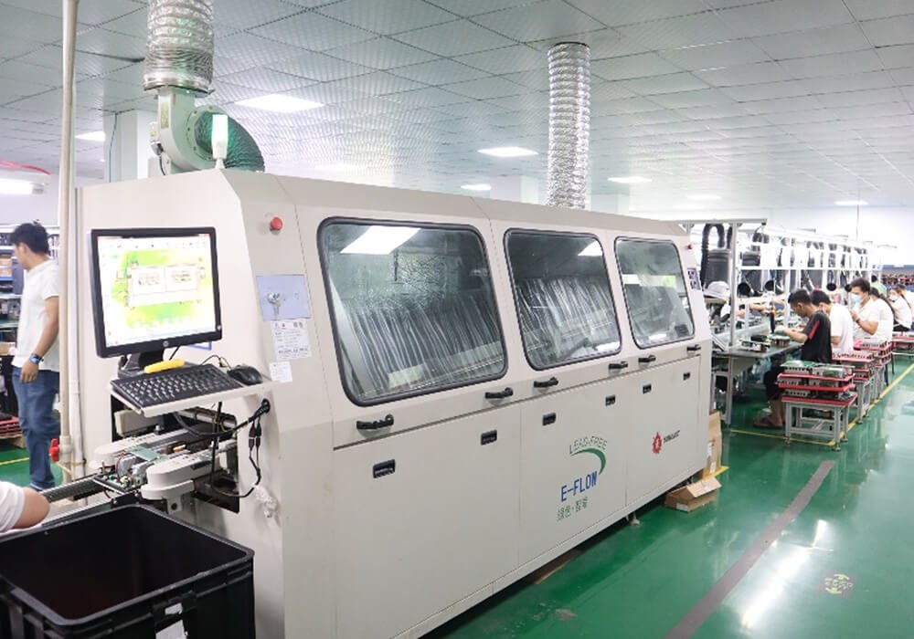
Wave soldering is an efficient solution for PCB designs with a large number of through-hole components that can be soldered in a single automated process.
It supports repeatable, high-volume production while reducing assembly time.
Selective soldering is widely used for mixed-technology PCB assemblies that combine SMT and through-hole components.
The process applies solder only to designated locations, minimizing heat exposure to nearby sensitive devices.
Press-fit technology creates reliable electrical and mechanical connections without solder by inserting compliant pins into plated through holes. This method is commonly used for high-reliability connectors and automotive or industrial applications.
THT Design and Build-Package Review
We will review whether the supplied data supports insertion, joining, inspection, testing, and repeat production.
Engineering Reviews:
- PCB, BOM, assembly drawing, and CPL revisions for consistency
- Finished-hole size, lead dimensions, plating, and tolerance compatibility
- Pad, annular ring, thermal connection, copper distribution, and solder-mask conditions
- Component polarity, orientation, seating height, lead protrusion, and reference designators
- Spacing for insertion, tooling, selective-solder nozzles, hand soldering, cleaning, inspection, and rework
- High-thermal-mass connectors, thick copper areas, large metal parts, and component temperature limits
- SMT and THT order, masking, fixtures, secondary heat exposure, and two-sided assembly constraints
- Test points, programming interfaces, functional-test instructions, and acceptance requirements
Through-Hole Assembly Process
We follow a structured and tightly controlled through-hole PCB assembly process to ensure high mechanical strength, electrical reliability, and repeatable quality.
1. Build-Package Intake
We will checks the Gerber, BOM, and test requirements. Our engineering reviews the component orientation, insertion access, thermal conditions, and acceptance criteria.
2. PCB and Component Preparation
PCBs and components are fabricated, sourced, or received according to the agreed material model.
3. SMT Pre-Assembly When Required
For mixed-technology boards, SMT operations normally follow the approved sequence before THT insertion.
4. THT Insertion and Joining
Operators insert and secure the approved components, then use the quoted manual, wave, selective, or other approved joining process.
5. Cleaning, Inspection, and Testing
Cleaning is planned from the flux system, material compatibility, coating requirements, and contractual cleanliness criteria.
6. Final Acceptance, Traceability, and Packaging
Final review checks the agreed workmanship, testing, records, labels, quantity, and packaging.
Inspection
We will define the selected methods, inspection coverage, sampling requirements, acceptance criteria, and quality records according to the project specifications.
1. Visual Inspection
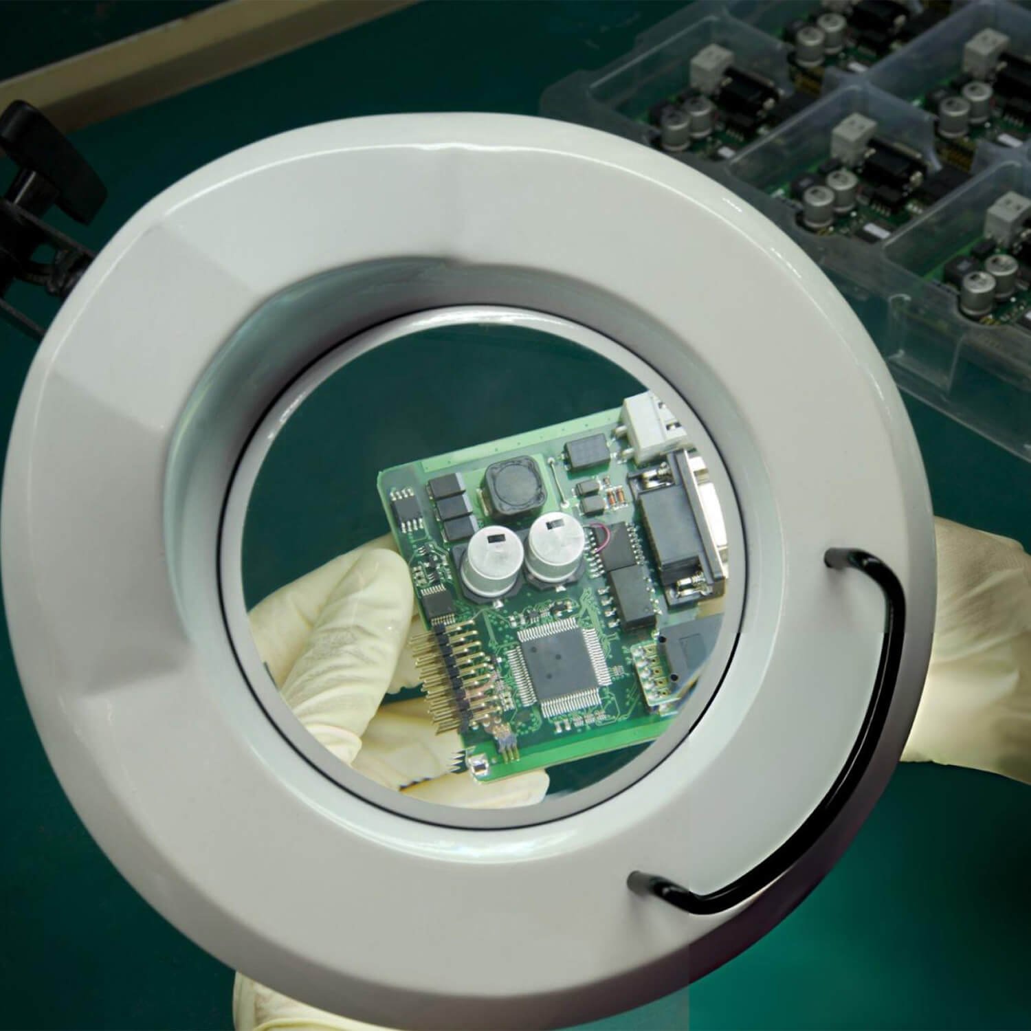
Visual inspection is the first step in verifying assembly quality. It checks component polarity, placement, lead condition, visible solder joints, physical damage, and contamination.
2. AOI
When applicable, we will use AOI to inspect component presence, orientation, and lead alignment.
3. X-Ray Inspection
X-ray inspection is used for selected hidden or difficult-to-access solder joints where visual inspection is insufficient.
4. Electrical Testing
Electrical testing, such as In-Circuit Test (ICT), checks accessible circuit connections, component values, opens, and shorts.
5. Functional Testing
Functional testing verifies that the completed PCB assembly performs according to its intended operating requirements.
6. Cross-Section and Destructive Analysis
We can do cross-section or destructive analysis to evaluate plated through holes, solder joint quality, and internal PCB structures.
Factory Glance
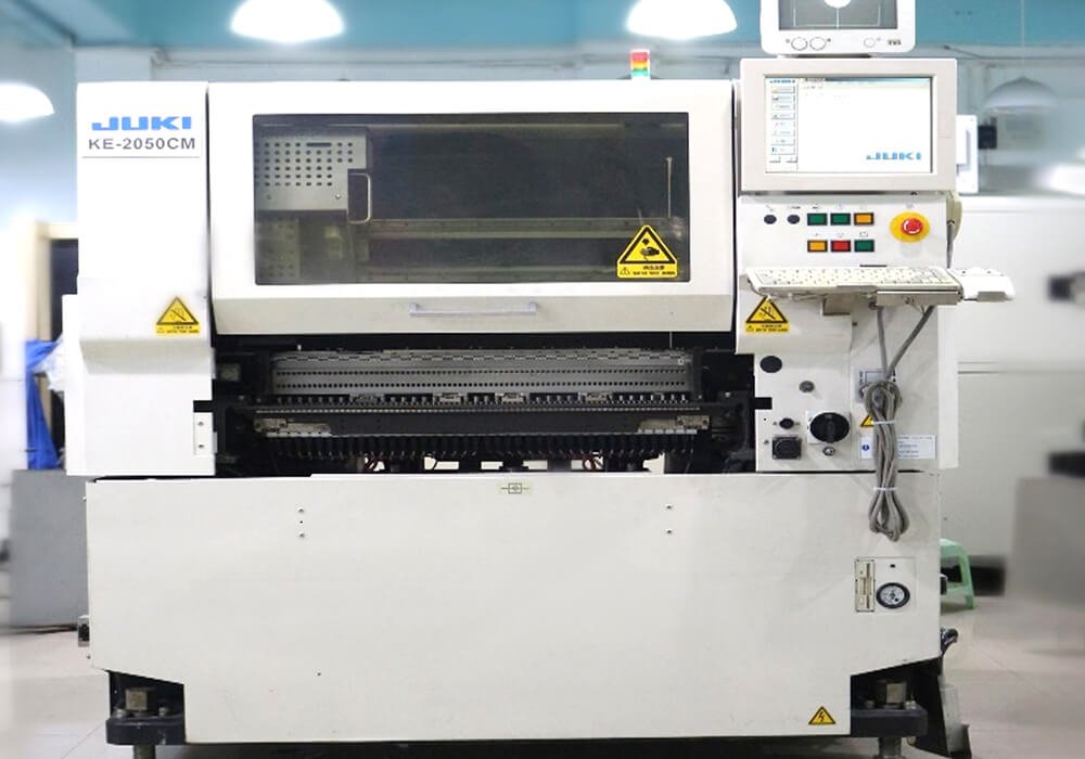
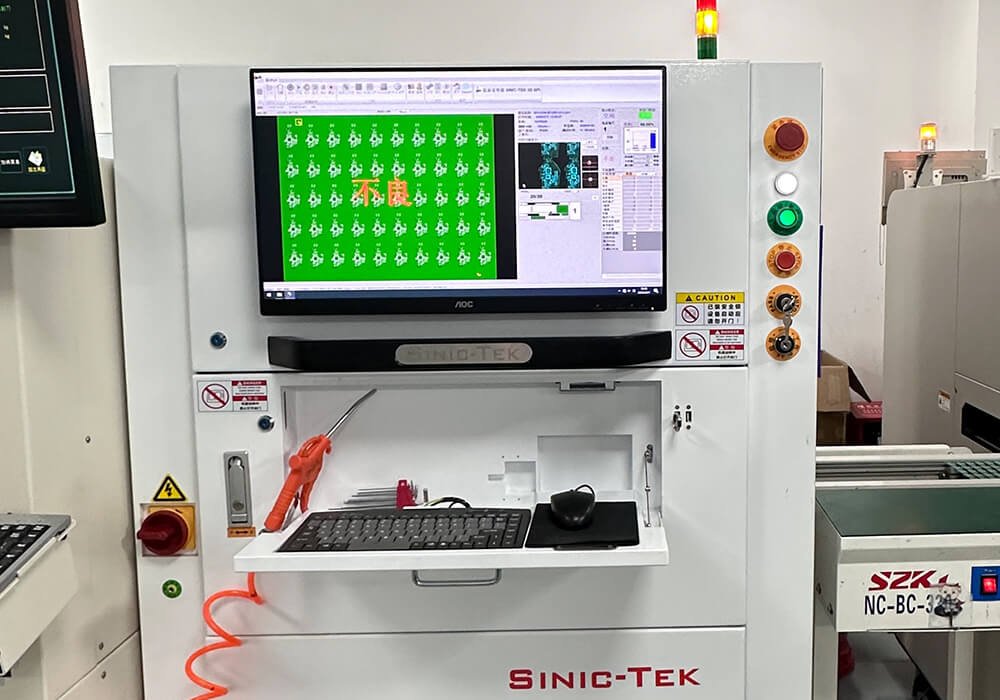
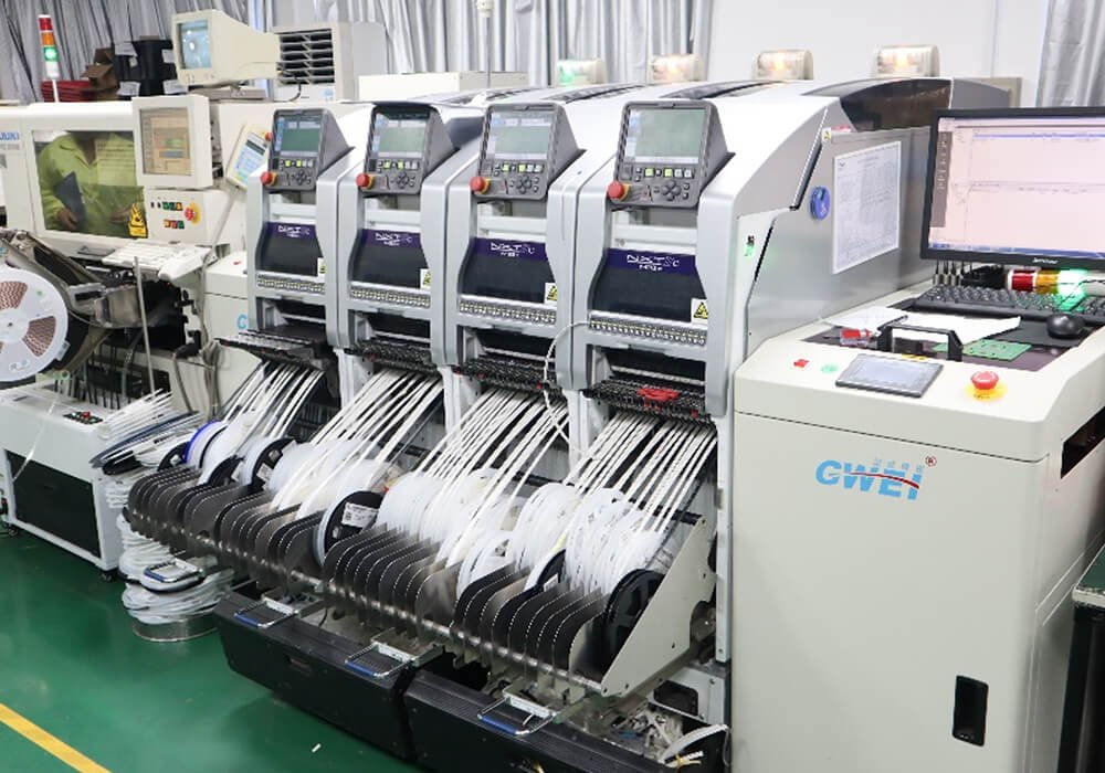
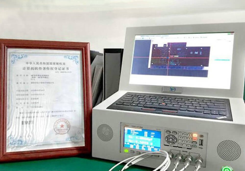
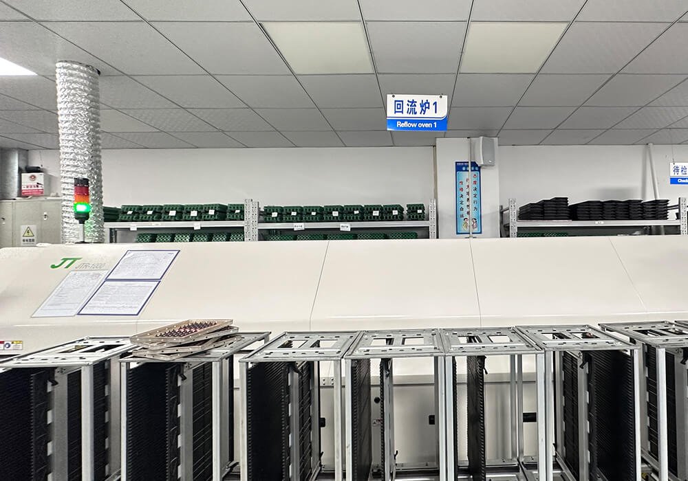
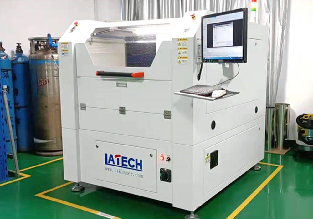
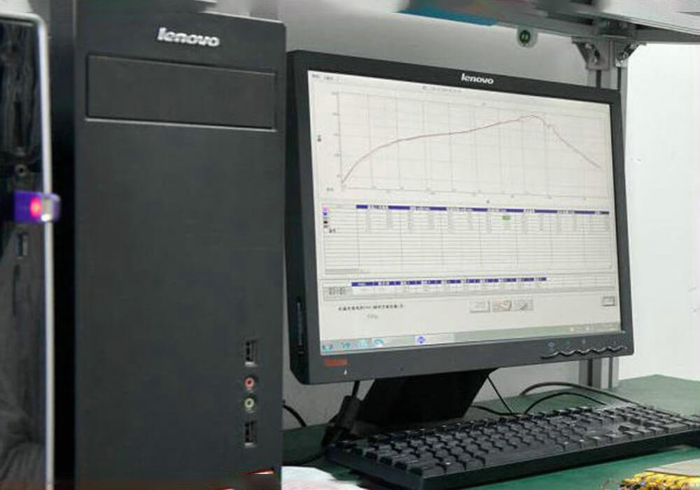
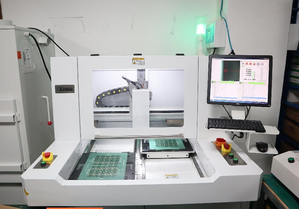
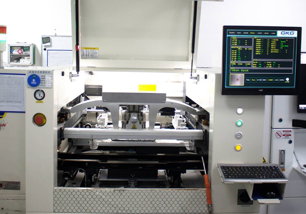
Our facilities are equipped with wave and selective soldering equipment, precision lead-forming tools, and ESD-controlled manual assembly workstations. Supported by trained technicians and RoHS-compliant manufacturing processes, we maintain consistent quality, process control, and assembly reliability across prototype and production builds.
Industries We Have Previously Served
Our through-hole PCB assembly solution are widely used in industries that demand high reliability, mechanical durability, and long operational lifecycles.

Automotive Electronics
We support automotive manufacturers and Tier 1 suppliers with robust PCB assemblies designed for harsh operating environments.
- Engine Control Units (Ecus)
- Battery Management Systems (BMS)
- Power Distribution Modules
- On-Board Chargers And Inverters

Industrial Automation
Industrial environments require durable electronics capable of continuous operation under mechanical and electrical stress.
- PLC
- Motor Drives And Servo Controllers
- Industrial Power Supplies
- Human-Machine Interface (HMI) Systems

Aerospace
We provide high-reliability assemblies for aerospace and defense systems.
- Avionics Systems
- Radar And Communication Equipment
- Navigation And Control Modules

Medical Electronics
Medical devices require precision, stability, and long-term reliability under strict regulatory standards.
- Diagnostic Equipment
- Patient Monitoring Systems
- Imaging Systems
- Laboratory Instruments

Consumer Electronics
For consumer products requiring durability and longevity, through-hole assembly offers added reliability.
- Audio Equipment
- Power Adapters
- Home Appliances
- Gaming And Entertainment Systems

Telecommunication
We support telecom equipment manufacturers with reliable PCB assemblies for network infrastructure.
- Base Stations
- Signal Amplifiers
- Network Switching Equipment
- RF Power Modules
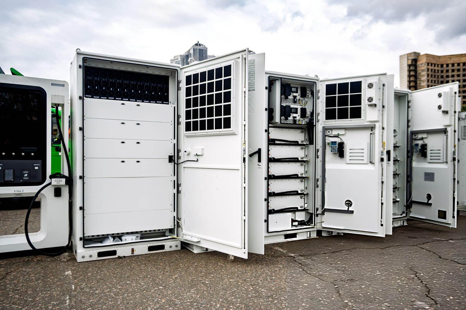
Energy Systems
Through-hole PCB assembly is ideal for high-power applications due to its strong mechanical and electrical properties.
- Switching Power Supplies
- Solar Inverters
- Energy Storage Systems
- Power Distribution Units
Fast Quotation
Our professional sales and engineering teams provide fast PCB quotes and technical support. Simply send us your Gerber files, BOM, and assembly drawings, and we will respond promptly with a competitive solution.
- Gushu Tangxi Second Industrial Zone, Shenzhen
- +86 755 2335 0814
- +86 135 1078 8094
- sales@pcbasail.com
FAQ About Through-Hole PCB Assembly
1. What files are required for a through-hole assembly quote?
Provide Gerber or ODB++ data, drill files, a BOM with complete manufacturer part numbers, an assembly drawing, target quantity, sourcing preference, and quality or test requirements. Mixed SMT and THT builds also need CPL data. Schematics, component drawings, programming files, fixtures, and packaging instructions may be required for the quoted scope.
2. Can PCBSAIL build mixed SMT and through-hole assemblies?
Yes. We reviews mixed-technology projects and defines the sequence for SMT reflow, leaded-component insertion, secondary soldering, cleaning when specified, inspection, and testing. Feasibility depends on component heat limits, side configuration, soldering access, tooling, joint visibility, and test access.
3. When should wave soldering or selective soldering be used?
Wave soldering suits layouts where many compatible THT joints can share a controlled soldering pass. Selective soldering suits local THT areas on mixed-technology boards or designs with components that restrict full-board wave exposure. Engineering selects the route after reviewing thermal mass, access, masking, fixtures, quantity, and acceptance criteria.
4. Can PCBSAIL build to IPC Class 2 or Class 3 requirements?
Class 2 or Class 3 requirements can be evaluated when the customer specifies the applicable standard, revision, addendum, product requirements, inspection coverage, sampling, and records. We confirms the achievable scope in the quotation. A general reference to IPC does not automatically make every process, operator, facility, or assembly Class 3 certified.
5. Can PCBSAIL source the PCB and components?
Yes. Projects may use full-turnkey, partial-turnkey, or consigned materials. The quotation identifies who supplies each item, which manufacturers are approved, how alternatives are authorized, and how shortages, attrition, customer-owned material, and excess inventory are handled.